A Daily History of Holes, Dots, Lines, Science, History, Math, Physics, Art, the Unintentional Absurd, Architecture, Maps, Data Visualization, Blank and Missing Things, and so on. |1.6 million words, 7500 images, 4.9 million hits| Press & appearances in The Times, Le Figaro, Mensa, The Economist, The Guardian, Discovery News, Slate, Le Monde, Sci American Blogs, Le Pont, and many other places… 5000+ total posts since 2008.

  • A Reverse D-Day, 1803

    JF Ptak Science Books  Post 2746  

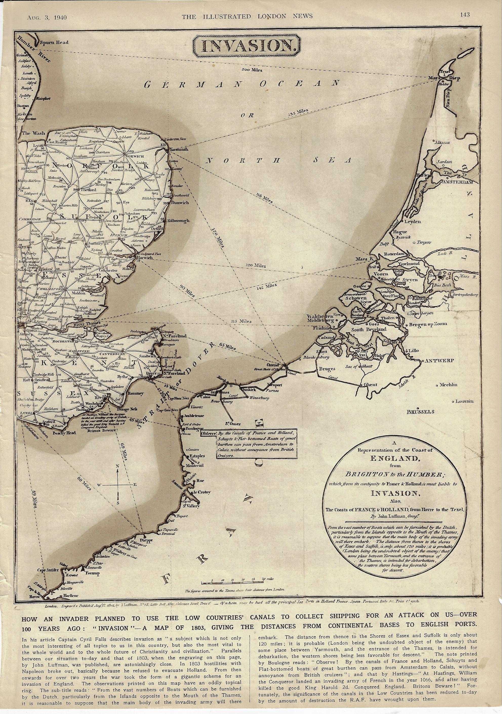
    There have been many D-Days in the history military terminology, but for almost everyone it refers to the Allied invasion of Normandy on 6 June 1944. In 1803 when Napoleon was in high form and making his way through Europe there was a wide concern in England that he would attempt a cross-channel attack and invade the country.  Which leads us to this map1 that I just found (again) in the Illustrated London News for 3 August 1940–the map entitled “Invasion”, showing the possible routes that the enemy might take in crossing the channel. 

    This was published at the time where the very real threat of invasion loomed like an angry low-ceiling mammatus cumulus, ready to break. Belgium, Luxembourg, and the Netherlands were defeated three months earlier, Dunkirk had just been sustained and the evacuation completed two months earlier; one month later, in July, the Battle of Britain had begun. It was not the French this time, but Germany–though the French had just weeks earlier surrendered without much fight and signed a disgraceful armistice with Germany, further weakening the very bad position of Great Britain. France was invaded in May and surrendered in June, an incredible collapse of what had just a few years earlier been Europe’s leading army, encamped behind the instantly obsolete Maginot Line.  It would be another 16 months before the U.S. entered the war, and another 46 months before the Normandy Invasion would cement the endgame for the war in Europe.  There was one gigantic good thing that happened in May–Winston Churchill became the Prime Minister. 

    Perhaps the editors at ILN sought to show the stoic Brits that they had been “there” (but now “here”) before, and nothing came of the Napoleonic threat. Of course there is almost no discussion of earlier attempts at invasion–though there is some fine print on the map quietly shouting “Beware Britons” about 1066 and all that.

    The odd thing about this map–made by J. Luffman and published 17 August 1803–is that I haven’t been able to find it online. The mapforum group has a very interesting entry on Luffman as well as images of a different map showing a much greater area.2 And so here it is–perhaps I’ve missed the thing, somewhere, but I just haven’t been able to find it. 

    The Luffman map comes very close to concentrating on the WWII D-Day theater of operations, the map extending as far to the SW as Le Havre, which misses by just 10 miles the Eastern Task Force beachhead at Sword.  

    Map invasion 1940

    Notes:

  • The Fossil Record of Duchampian Motion–an Early Image in Spatial Time (1884)

    JF Ptak Science Books   Post 2747

    MArey May 1884_2_

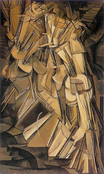
    This is one of those times where science precedes art–that’s the least significant aspect of this image, as the folks seeing it in 1884 couldn’t see into the future didn’t know that they were looking at what may pass for prehistoric fossil record of Duchamp’s 1912 Nude Descending.  The Duchamp would cause trial and occasional outrage in much of the artworld due no doubt to it challenging aesthetic–I don’t know what the readers of the Compte Rendus thought when they saw this image, but I suspect it did not involve evaluating its artistic impact.

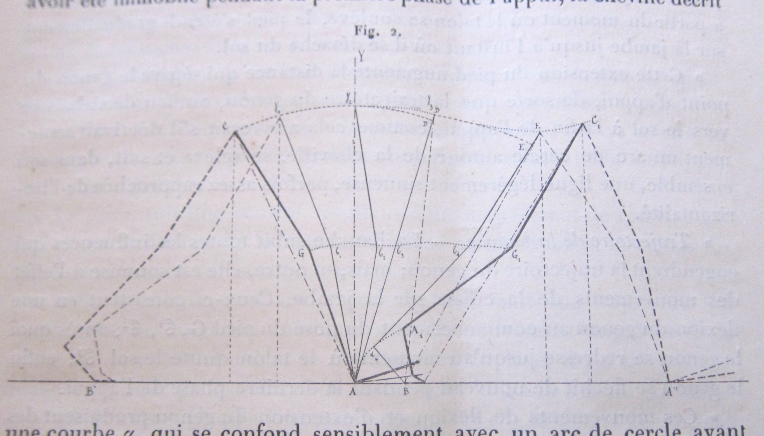
    This is the work of Etienne Marey (who has made a number of appearances on this blog), a very smart and versatile guy who would go from physiology to cinematography to aerodynamics in the course of his life and be a leader/pioneer in each field.  Marey published this “strobophotograph” in his article “Analyse cinematique de la marche” in the Comptes Rendus on 19 May 1884–this was a brilliant effort in the analysis of human locomotion by making a dozen or two exposures on a single photo sheets of a reflective-outlined walking figure. This was different from Marey’s birthyear and deathyear buddy, the other motion picture pioneer, Eadweard Muytbridge (1830-1904 for both). Marey introduced his “chronophotography” and studied aspects of movement and motion that had been dispersed to human history because of the inability to observe and record them–with Marey, that issue necessary for the beginning of real scientific discourse was to a large extent solved. 

    Duchamp_-_Nude_Descending_a_Staircase

    Marcel Duchamp’s Nude Descending a Staircase, 1912, via Wikicommons

     There are more applicable Marey images for the Duchamp–for example his series on a single sheet of a naked woman descending a short set of stairs–but the image above has more aggregated motion in a confined space sense to it, so I’ll stay with the sense-impressions than the more-visual ones. 

    And here’s Marey’s  modeling of the action:

    Marey May 1884

    In any event, I just wanted to pass on this quick note on some seldom-seen Marey images…

  • Looking for Bastogne (1939)

    JF Ptak Science Books   Quick Post

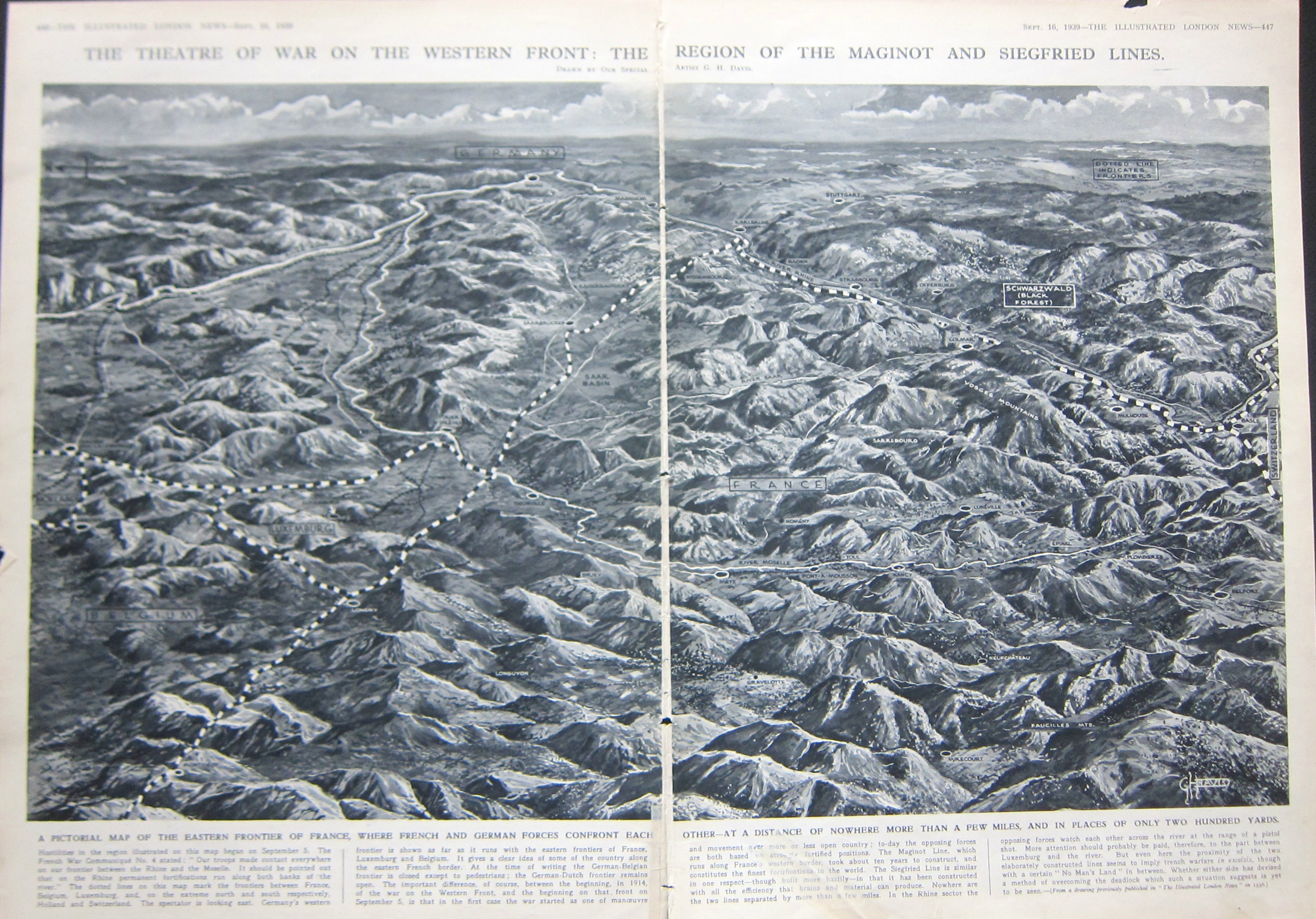
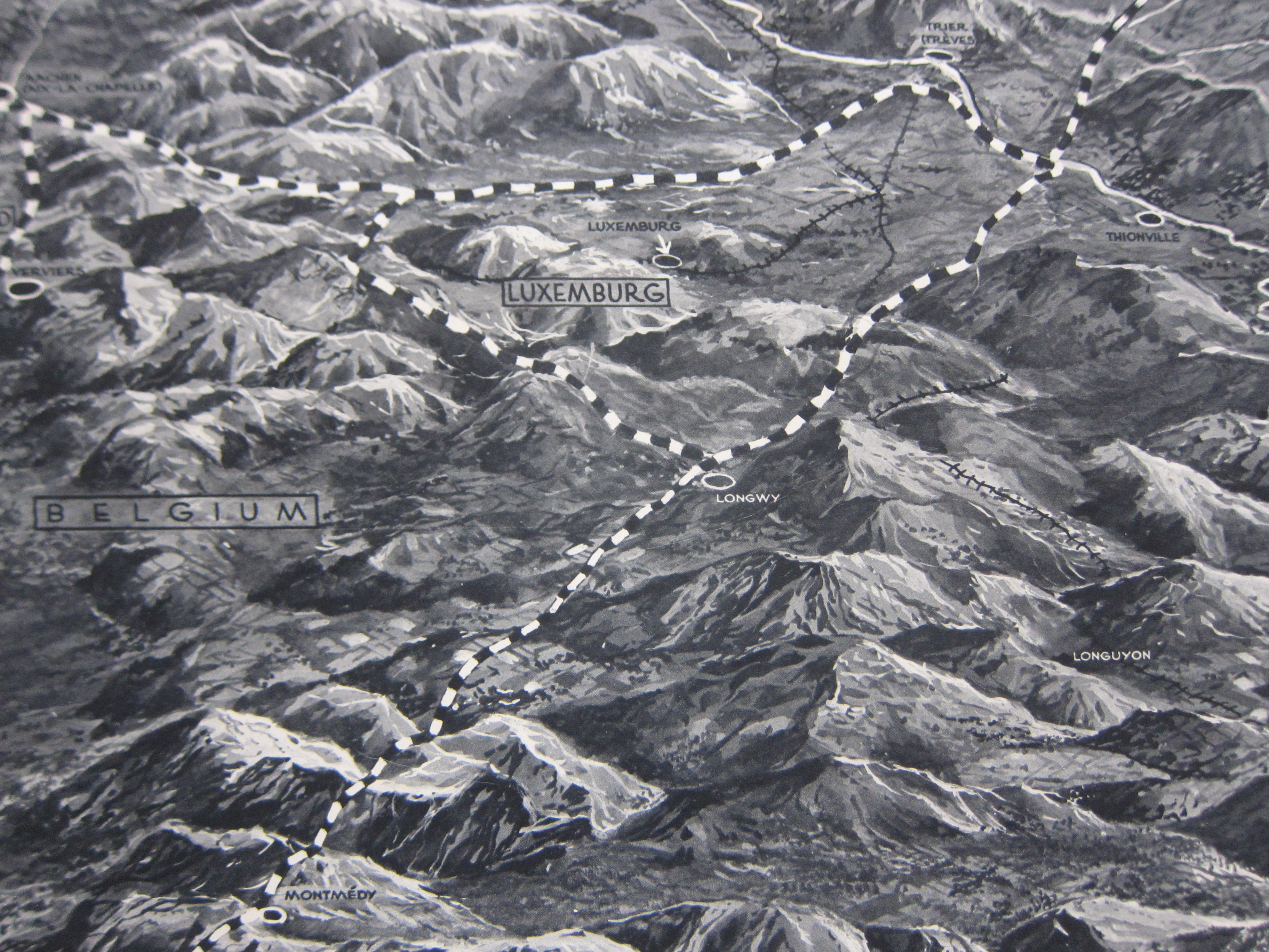
    This double-page map from Illustrated London News caught my eye–it shows “the theatre of war on the Western Front” at the end of the second week of the European war, 16 September, 1939, just five days after the war had been freshly defined for the first time as “World War II”. (From the OED: “1939   Time 11 Sept. 38/1   ‘Some of the diplomatic juggling which last week ended in World War II was old-fashioned international jockeying for power.’”) It is an interesting oblique view (north to the left) created by the great ILN illustrator, George H. Davis, showing the borderlands of Belgium, Luxenbourg, France, and Germany, the first three soon to be overrun. The map does seem to present a good bird’s eye for the region, and what I set out to find was the Ardennes–soon to come to life again as an unlikely entry point of attack to France, and then again to the Germans come Christmastime 1944.  Part of the Ardennes is seen at the lower left, though not identified. Triangulating the towens of Longwy, Longyuon, and Luxembourg City, I’d place the town of Bastogne at about the “G” in the title for “Belgium”.  The town isn’t on th emap now, but in five years, everyone will know where it is, named or not.  

    Maps WWII ILN 1939 Ardennes

    IMG_9195

  • A Tough Place to Work: in a Box, Submerged, Digging Muck and Boulders from a Riverbed (1870.)–Expanded

    JF Ptak Science Books   (Expanding Post 2686)

         Before the Brooklyn Bridge (begun in 1870 and opened 1883) became its incredible self, there was a lot of King-Hell work to be done before the recognizably visible bridgey part could be started. Amidst all of the thousands of bits that had to be figured out before a stone or cable could be moved, before the bridge-builder John A. Roebling (1806-1869) could begin to build, he had to construct the gigantic towers which were the great heart of the bridge on solid footing in the East River, and in order to that you had to get to the bottom of the river and then dig from there.  Roebling found the solid that he needed, but it was 80 and 40 feet below the river (on the NY and Brooklyn sides),  and so it came to pass that Roebling became one of the few U.S. experts in building the apparatus that would allow you to dig down under the bottom of a river. (Roebling became an engineer at a time when there really weren’t very many of them, and the profession was quite small–according to the U.S. census there were only 512 in the U.S.; in 1880, when the bridge was nearly completed, there were 8,600. This number expanded to 45,000 in 1900 and then 230,000 by 19301.)

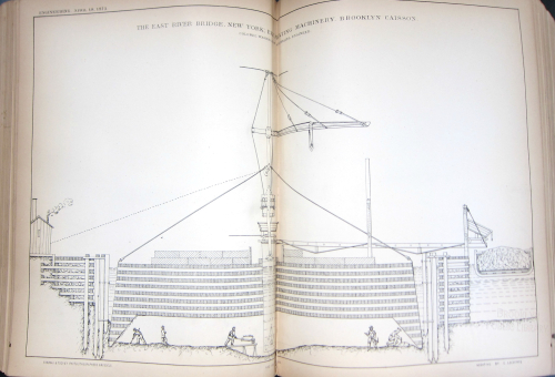
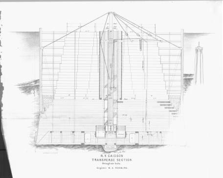
         He created what was basically an upended box, an enormous, 180’x120′ (with a 9′ ceiling that would be 6.5′ at the end) half-city-block/half acre open-bottom box, called a caisson2.  The idea was that as it was sunk to bedrock the entire structure would be braced with hundreds of thousands of bricks and then filled completely with cement. That would be the base for the 30,000 tons of masonry blocks (each about 4-7 tons) that rested on top of the 15 layers of massive timber ceiling that rested upon the brick and cement that sat on bedrock. 

         In the course of excavation the caisson would be filled with pressurized air, and then with its various modes of entry it would accommodate three shifts of about 80 men inside it, shoveling away at the muck and picking away at boulders, digging their way into the river bottom.  (Soon enough they would be blasting the boulders in the pressurized air compartments of the caisson, encapsulated by timbers waterproofed with highly combustible materials that were covered by pitch and protective layers of this and that, but that is another of the very many engineering stories that could be told in depth and not to be included in this short note.) 

         The conditions for work were oppressive, and the pressurized air was difficult to work in and had long-term ill-effects on the body for some,  the contrast between light and dark was very stark and difficult with hard shadows, the workspace demanded an immediate body-soaking sweat, the noise of the general work (excepting the blasting and boulder-breaking) was “very considerable”, the muck and water was occasionally a foot high,  and the work itself was very physically demanding.  There were over 2500 men who worked in the caissons over the 10 months that they were in use, which according to David McCullough in his excellent The Great Bridge3 meant there was an enormous turnover, 100 men a week…and no small wonder. All for $2/day, which was a little better than standard pay for laborers (and equal to about $60/day in 2017 dollars so far as I can reckon, which is sorta/kinda minimum wage for 2008.)
    Brooklyn caisson large engineering 1873

    • [Image Source; Engineering, 1873]

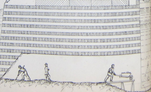
         So here they are, the guy on the right is hauling the muck to an elevator shaft at right (more visible in the full version of the woodcut, following), while another fellow shovels, and a third man strands there surveying the scene with arms folded in a pose recognized world-wide at construction scenes.  The little squares above them show the cross sections of one row 12″-thick lengths of cut lumber (laid on top of another layer of the same running at a right angle, making 15 layers in all) on top of which stone would be placed. 
    Brooklyn Bridge Caisson Engineering 1873


         It should be noted in fairness that the supervisors hardly leaned on a shovel or struck an heroic pose in the Brooklyn Bridge construction. Washington Roebling, the son of John A. Roebling and who inherited the project after his father’s very untimely death in 1869 and who was one of the best-suited men in the country to take on the job, spent many weeks in the caissons doing whatever he saw fit to be done. He was one of the relatively few workers there who was overtaken by the demands of the pressurized air, and spent the rest of his life (he died in 1929) dealing with the aftereffects of it.  

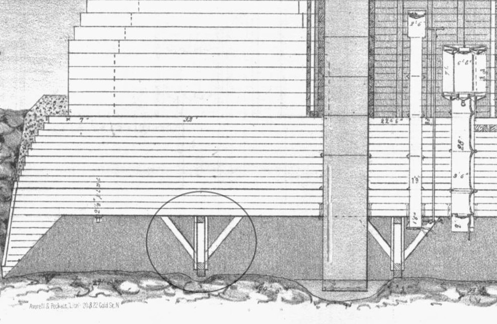
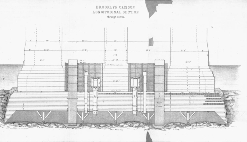
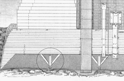
         There were air shafts and elevators and pneumatic tubing to pull out excavated earth, and as the workers dug down, the caisson would sink, and with each movement enormous blocks of granite would be placed on the top of the caisson to help it sink further.  And so this would be the process, digging down through a silty river bottom, pulling out the very heavy muck, the caisson moving down as the earth was removed, continuing the process until bedrock was reached. The caisson movement though proved to be a lot more involved than the initial design, where the edges of the thing were supposed to eat and push their way into the earth as ground was removed from around the base, with the enormous tonnage above providing the weight to push the whole thing. But it really didn’t work out that way, and the caisson(s) for the most part didn’t work their way into the riverbed. What happened was that numerous chock blocks were place and large hewn timbers place on top of them to the caisson’s ceiling. And then, once the river material was removed from the perimeter to a certain depth, the blocks would be knocked out from underneath the support, and with practice, the entire structure would set into place, moving down. And then the process would begin again, over and over.

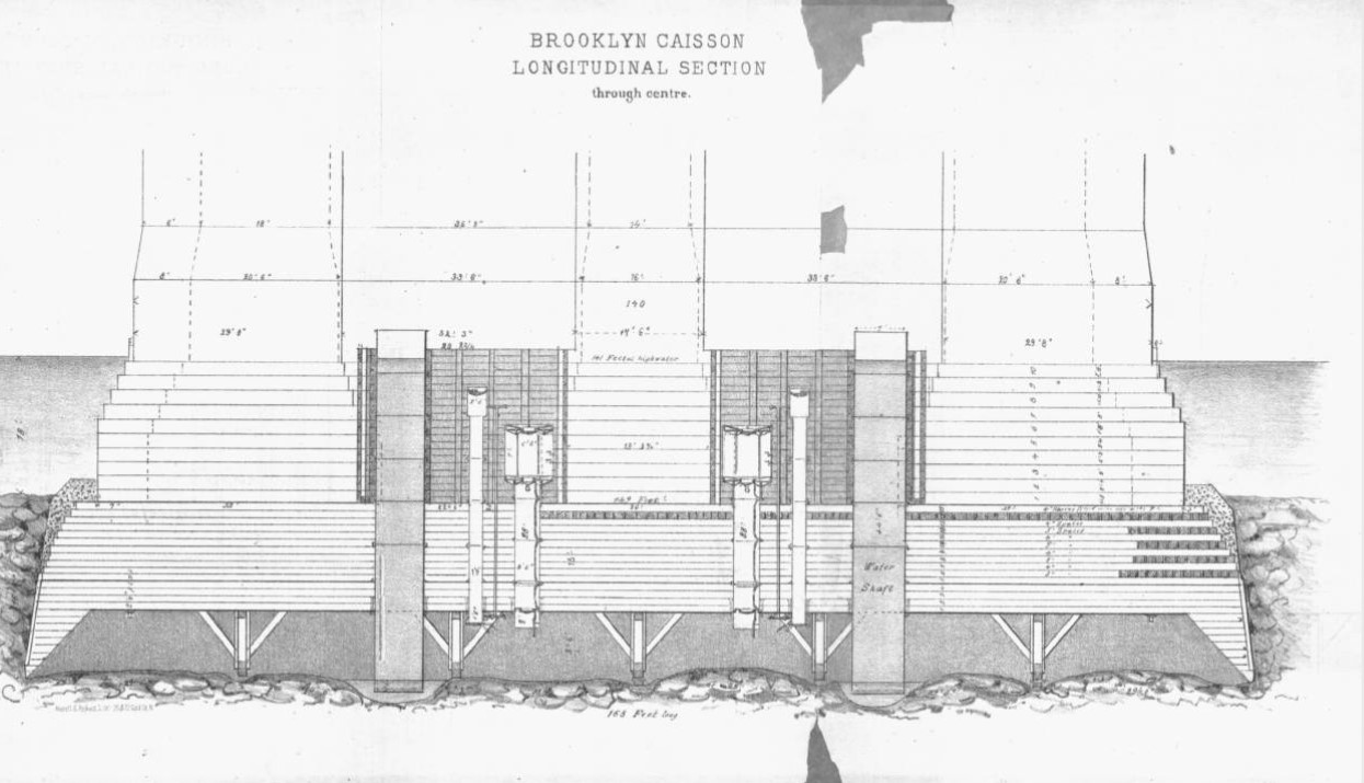
        This is another cross section of the caisson, followed by a detail showing the blocks:
    Brooklyn bridge caisson W Roebling

    • [Image source, for the images immediately above and below:  W.A. Roebling, Pneumatic Tower Foundations of the East River Suspension, [the caissons of the Brooklyn Bridge] New York, Averell & Peckett, 1873. The full text is available from Lehigh University http://cdm.lib.lehigh.edu/cdm/ref/collection/bridges/id/1406]

    And the blocks and supports, the blocks being knocked out once all of the mud and stone had been removed from the circumference of the caisson:
    Brooklyn bridge caisson footer detail

    And then, it was all filled in, more weight was added to the top of the caisson, until that special engineering sweet spot was reached that allowed you to start building the bridge’s towers from which the bridge span would be suspended.

    This was a very difficult job and absolutely vital job, not the least of which was the problem of decompression sickness, which affected many dozens of workers, and which was not well understood.  

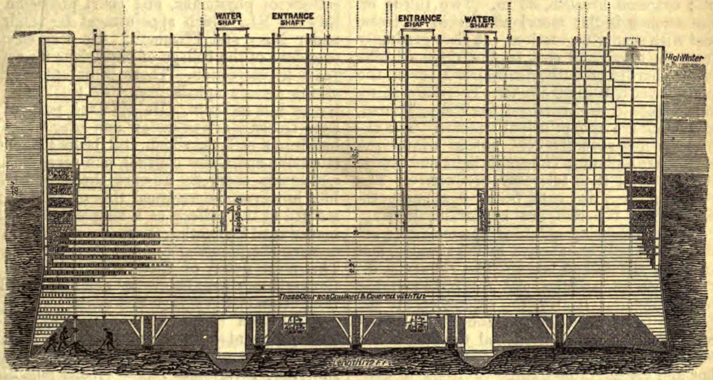
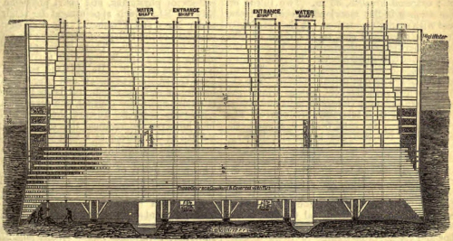
     Another image, this from The American Cyclopedia, showing the caisson at a more developed stage, and feeling that much more suffocating, and I think communicates the idea of extreme weight a little better than the others:
    Brooklyn Bridge Caisson wikimedia

    • [Woodcut/drawing illustrating caisson used by W. A. Roebling in the construction of the Brooklyn Bridge. The American Cyclopædia, v. 3, 1879, p. 557 (Fig. 2).]

         I really haven’t gotten to the most difficult jobs on the bridge. Almost at the very end of the work on the Brooklyn side there was a fire in the caisson. Up until this point there had been a number of small fire that were quickly extinguished. But nearly at completion a worker managed to ignite one of the combustible materials used to sheath the ceiling, and a small section caught fire. Given the pressurized oxygen and other factors the fire progressed to An Enormous Situation. Long story much shortened, the fire was thought to be put out until after one of the continuing series of investigation in making sure that the fire was out revealed that in fact it was not–to make matters worse, it was mostly invisible and smokeless.  Many complications and complex solutions later, the fire definitely extinguished, the time had come to finally repair the damage. The fire had eaten its way through several of the 15 layers of the wooden beamed ceiling, and those damaged parts needed to have the crystalized carbon scraped away so that the then-vacant area of wood could be filled with cement. And here it comes: it fell to 18 carpenters to pull their way as far as possible through the burned-out sections of the ceiling to scrape and chip away the burned parts. That means they were underwater, underground, in a cavernous submerged room with pressurized air, and crawling through wormholes in a 15′-thick wooden ceiling on top of which rested 30,000 tons of stone.  That, I think, was the toughest job done on the bridge. 

         30 workers were killed in various accidents during the construction of the bridge. Many considered that a bridge wouldn’t be safe unless there was some fatal blood spilled over it…and many considered that first victim to be John Roebling himself. He met his end before the physical work had been started on the bridge, killed because of a rookie situation he let himself into, he toes crushed by a ferry which led to tetanus and lockjaw, the old man dying a miserable death. He made notes and suggestions on the building of the bridge right up until the end, through the horrible stiffening of limbs and muscles as a result of the lockjaw. I guess he could’ve been considered the bridge’s first martyr. 

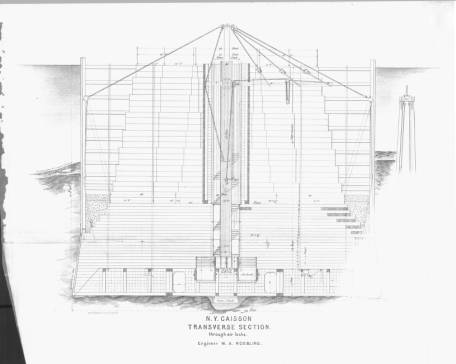
    And to balance things out a bit, here’s the transverse section of the caisson:
    Plates__Page_9

    • [Image source:  W.A. Roebling, Pneumatic Tower Foundations of the East River Suspension, [the caissons of the Brooklyn Bridge] New York, Averell & Peckett, 1873. The full text is available from Lehigh University http://cdm.lib.lehigh.edu/cdm/ref/collection/bridges/id/1406]

    Notes:

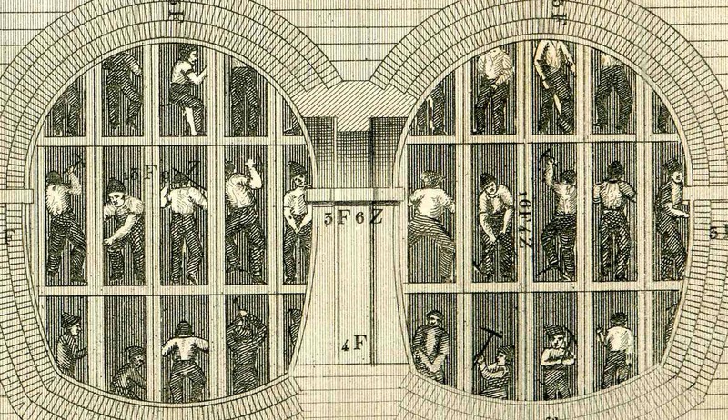
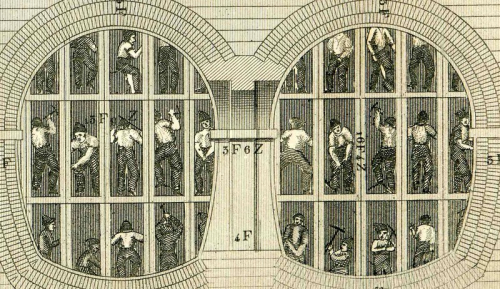
    I can’t help but include another image of a hard place to work, this one for the Thames Tunnel (from my post here: https://historyofideasblog.com/thesciencebookstore/2012/08/beautiful-technical-illustration.html)
    Tunnel detail thames


    1. Cecelia Tichi, Shifting Gears, Technology, Literature, Culture in Modern America. Chapel Hill, 1987, p 104. 

    2. “Caisson:  in architecture, a panel sunk below the surface in soffits or ceilings. In civil engineering, the term is applied, first, to a hollow floating box, usually of iron, which serves to close the entrances of. docks and basins; and second, to a box-like structure used in constructing or sinking the foundation of piers under water. Of the latter there are at least three different varieties: the ordinary, the bottomless or open, and the inverted, which includes the pneumatic. 1. The ordinary caisson is a large box with bottom and sides, made of timbers or planks, in which masonry is built and sunk to its desired position under water.”–The American Cyclopædia, v. 3, 1879, p. 557

    3. David McCullough, The Great Bridge, the Epic Story of the Building of the Brooklyn Bridge, Simon & Schuster, 1972. 

    For excellent source material see: W.A. Roebling, Pneumatic Tower Foundations of the East River Suspension, [the caissons of the Brooklyn Bridge] New York, Averell & Peckett, 1873. 
  • Unexpected Beauty in Antiquarian Homemade Bindings

    JF Ptak Science Books   Quick Post 

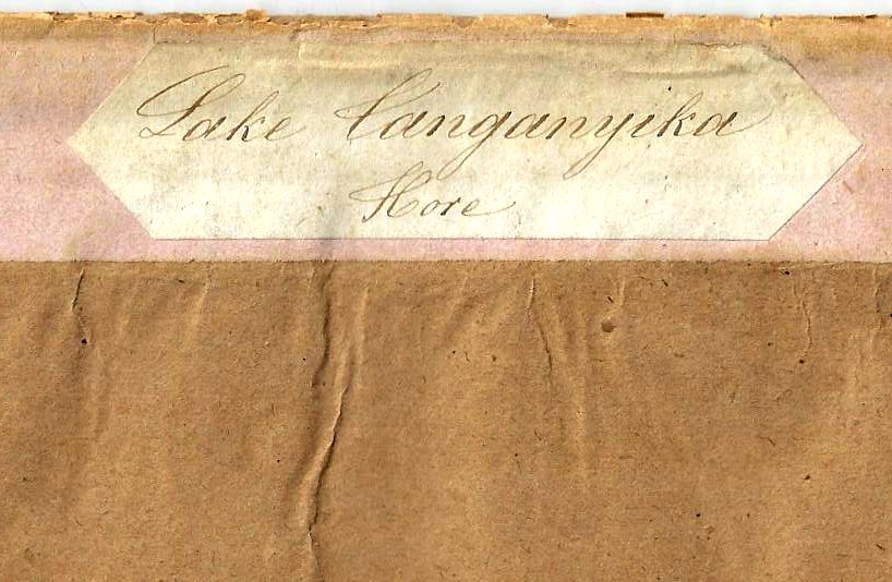
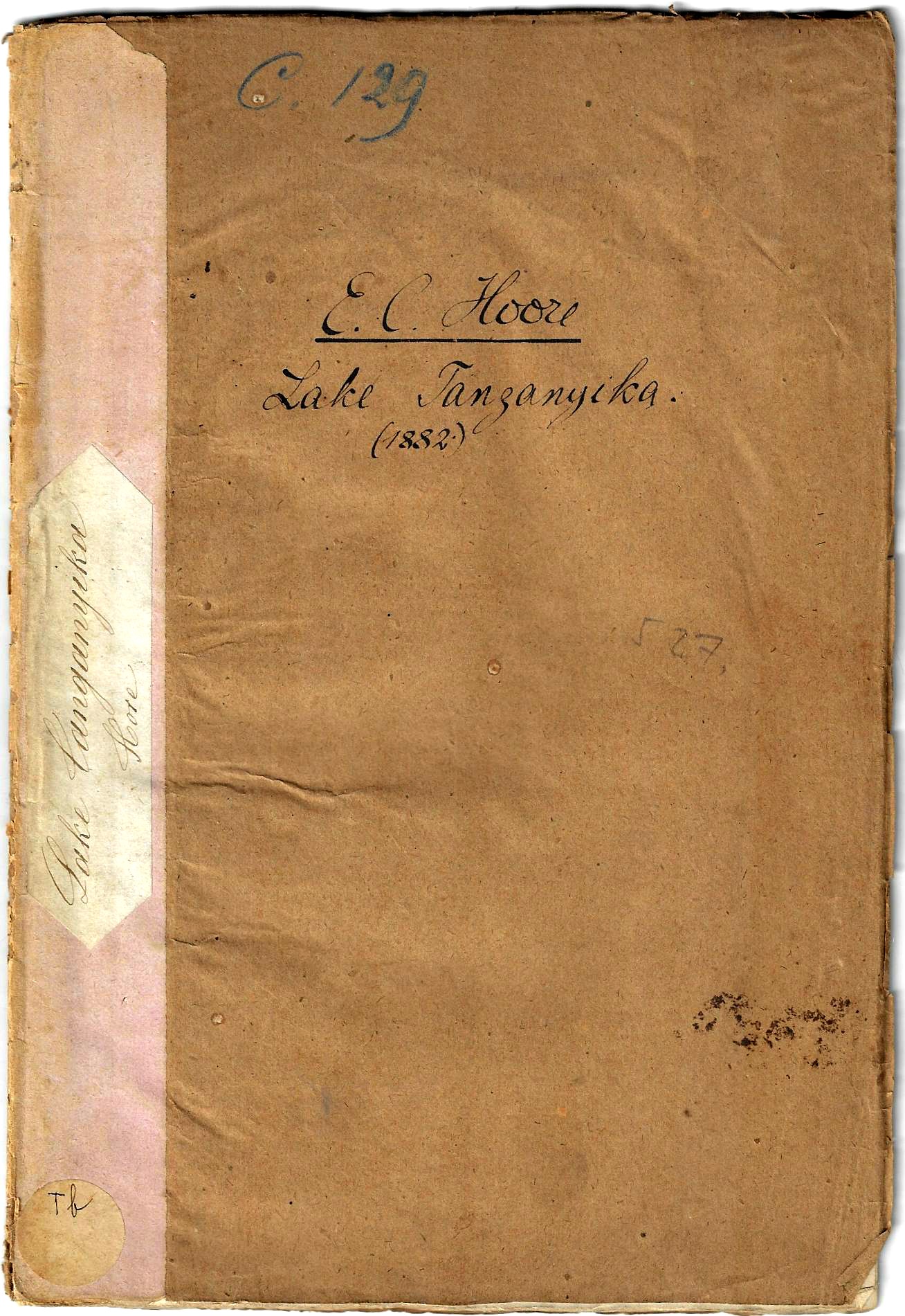
    There is a special beauty that comes with the imperfection and homemade qualities of an antiquarian bound-at-home book or pamphlet. I think that much of the time–in my experience–these bindings were made of whatever was available. Their irregularities can be charming, lovely even, the more imperfect but working/workable their attempts present an admiration for that amateur’s work so long ago. And so tonight I’m just going to quickly share one of these examples that just bobbed up–a homemade for a report from the Royal Geographical Society (1881) on Lake Tanganyika:

    Books covers Lake Tanganyeka detail


    And the full frontal:Books covers Lake Tanganyeka

  • Comparing Building Heights: the US Capitol, Statue of Liberty, and Trinity Church, in an Unexpected Chicago Skyline (1894)

    JF Ptak Science Books  Quick Post

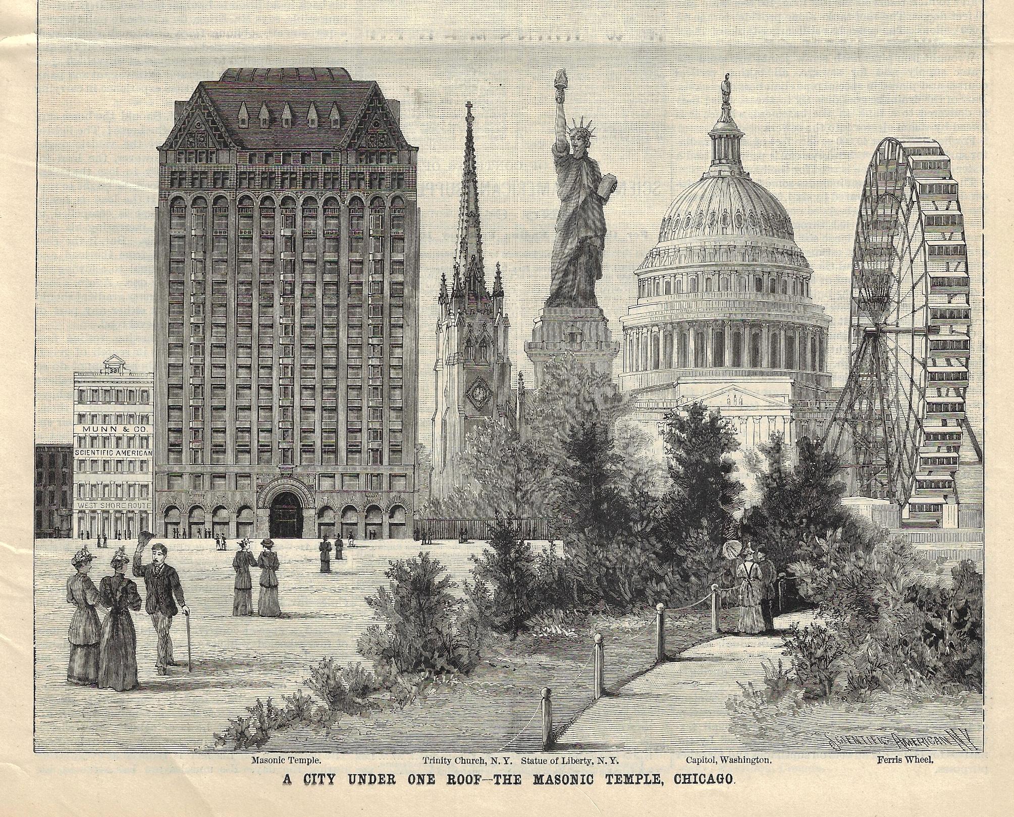
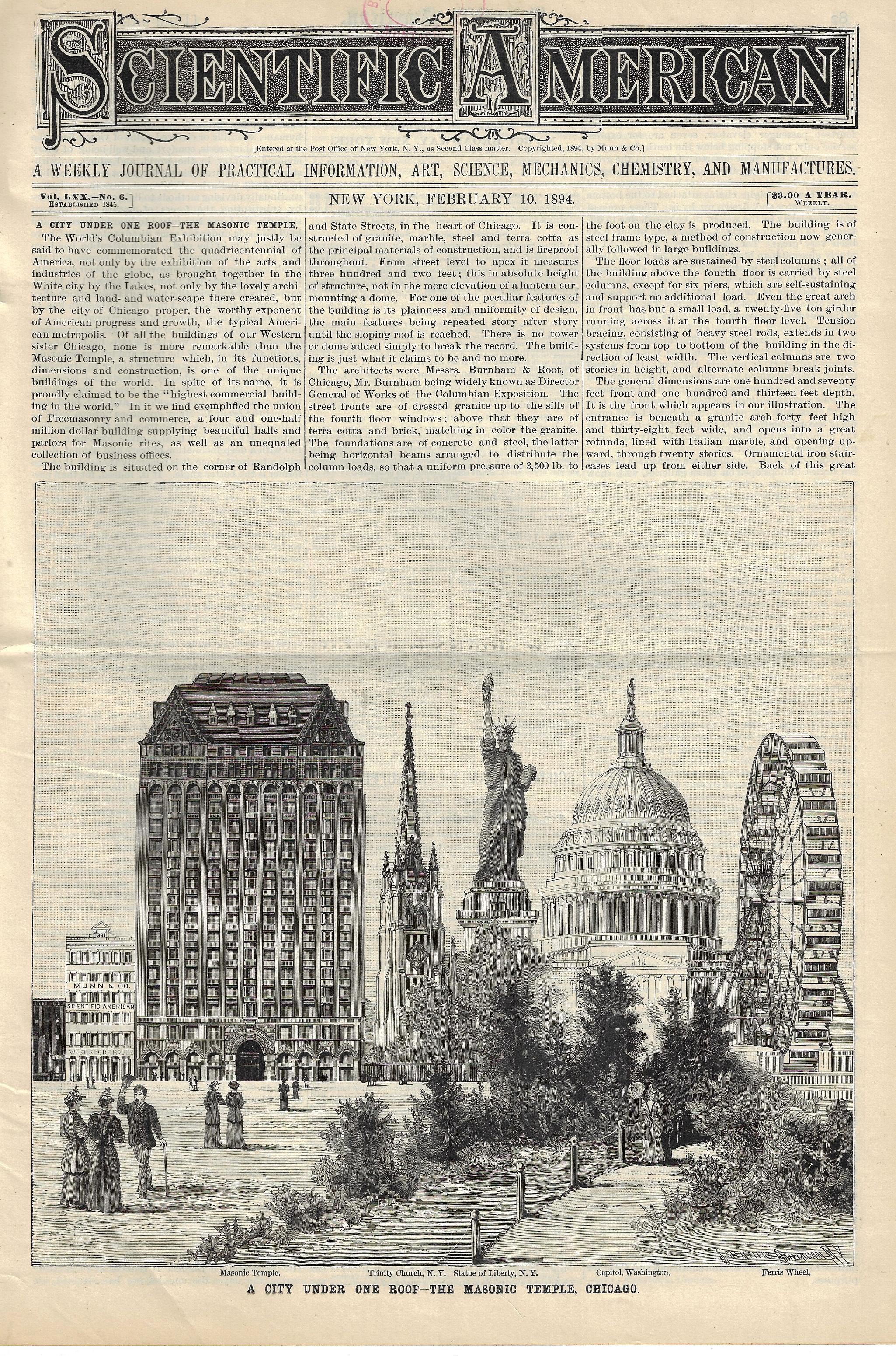
    In the several comparative heights of buildings images that have been posted to this blog in which buildings are compared to other buildings (and not enormous loaves of bread, or ears of corn, and so on) it turns out that many of them are set in a generic or fanciful landscape. Few that I can recall compare one building to several others in situ, as it were, using the area in which the building of note exists–and the example below yet again is one of those created landscapes. The building is the Burnham and Root Masonic Temple, in Chicago, and when it was built it was right in the heart of the city, without a field in the foreground. When completed in 1892–just in time for the Columbian Exposition–it was the tallest commercial building in the world, and also one of teh world’s tallest structures. The editors of the Scientific American commissioned this comparative, showing the new building (302′ high) in relation to the great Ferris Wheel in Chicago (288′), the U.S. Capitol (288′), the Statue of Liberty (301′), and Trinity Church (284′). Just for the sake of it the artist included the Broadway offices building for the Scientific American printer, Munn & Co., to the left of the Masonic Temple.  

    I have basically nothing to say about the building, not knowing it at all, and am just passing along this fine comparative image. (There are numerous pages devoted to this structure online.)  

    Source: Scientific American, 10 February 1894. 

    Sci Am 1893 dataviz detail

    Sci Am 1893 dataviz comparative height

  • Prof. Langley’s Aeroplane of 1893

    JF Ptak Science Books  Quick Post

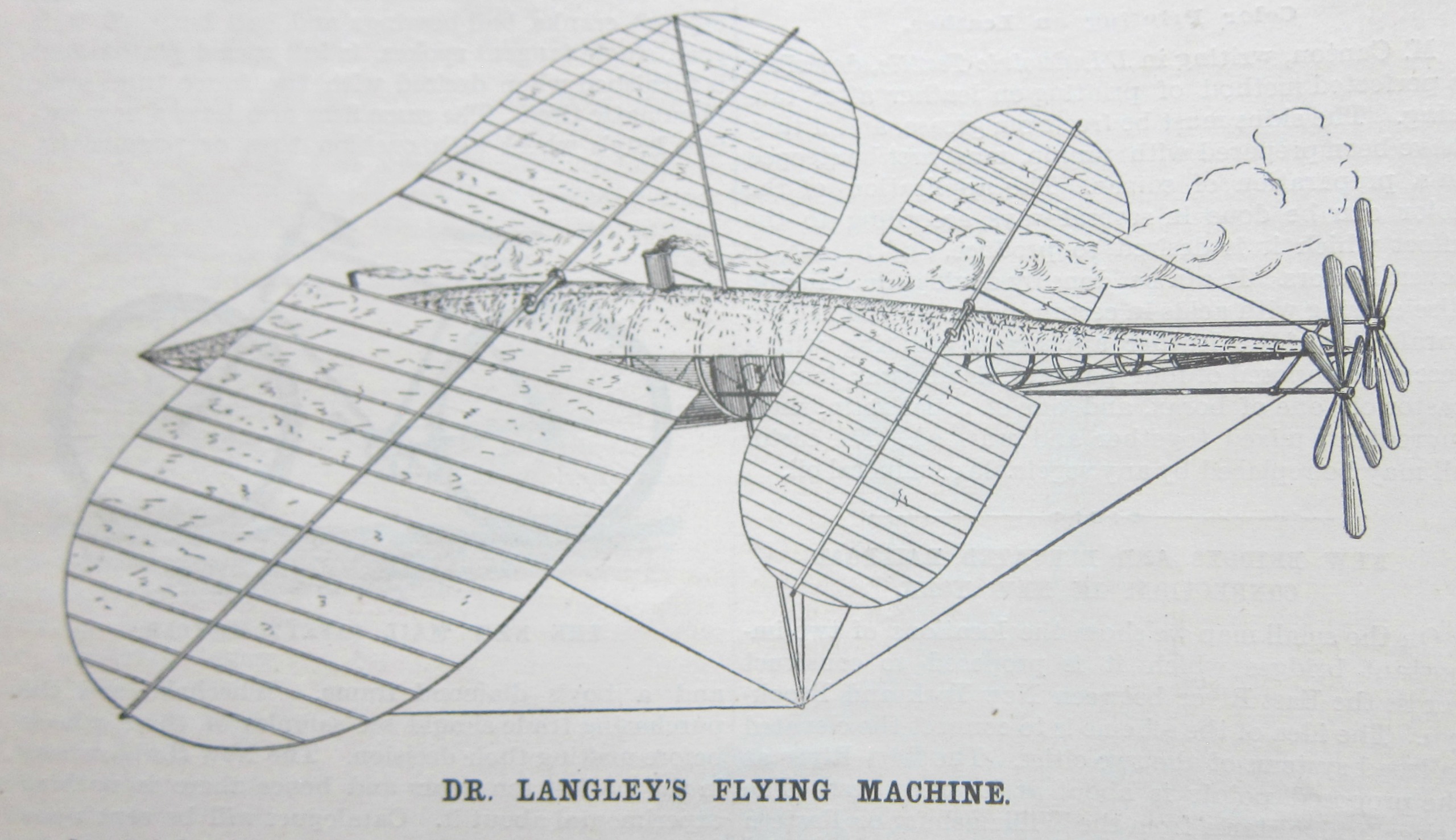
    In the Department of Victorian Understatement, the example following would be ranked…nominal. This was a general leading statement on a short one-page review of Samuel P. Langley’s1 model flying machine, found in the pages of the Scientific American for 22 April 1893 by H.E. Mead and quoting from the New York Herald. This is one of Langley’s earliest physical attempts at a flying machine, coming after four years of work (the same year work was commenced by Hiram Maxim and with the more mature work of Octave Chanute), the drawbacks of which began the article’s review:

    • “The only apparent drawback to this particular method of aerial flight is in maintaining an upright position of the apparatus, free from the ground, until sufficient velocity is attained for soaring ; and the means of alighting after flight. Other than the above mentioned difficulties (for which Professor Langley may have provided), the principle seems feasible, more especially when backed by so careful and competent authority.”

    Sci Am 1893 Langley flyer

    So, basically, it seems that what the machine was wanting was the ability to fly and land. This was never meant to hold a pilot, and was entirely experimental.  The characteristics of the model:

    • “It is 15 feet in length and 5 centimeters (or practically 2 inches) in diameter. To give rigidity to the skeleton, longitudinal ribs of stiff steel are provided, intersected at intervals by cross ribs of pure aluminum, the result being a lattice framework of great strength.”
    • “There are four boilers of thinly-hammered copper, weighing a little more than seven pounds each, and they occupy the middle portion of the fish Screws of various pitches and ranging from 20 to 80 centimeters in diameter have been experimented with, but it is not yet definitely determined which shall be adopted for· trial. With the smallest the engines develop a speed of 1, 700 revolutions a minute. With the larger ones the speed is somewhat decreased. A thin jacket of asbestos covers the upper portion of the body of the fish.”
    • “The wings, or aeroplanes, are sector-shaped and consist of light frames of tubular aluminum steel covered with China silk. The front one is 42 inches wide in the widest part and has an extreme length of 40 feet from tip to tip. The rear one is somewhat smaller. Both aeroplanes are designed to be adjustable with reference to the angle they present to the air.”

    It is interesting to note the attention this short perspective gave to the security and secrecy of the research:

    • “At the (Smithsonian) institution the strictest injunctions were laid on the watchmen to keep all intruders off the scent. The watchmen themselves were instructed to turn their backs or walk to the other end of the corridor when word was passed from the chief that some article was to be conveyed to or from the secret chamber.”

    To be fair about this some amount of secrecy was involved given the status of the kookiness in which much of the general public view the pursuit of flight–or at least the construction of large, relatively heavy models like this one. Langley had an enormous reputation to protect, and one part of that security was to keep that intact while the aeroplane was in its developmental phases, keeping the project free from derision which may have caused a problem so far as funding was concerned. That said,  Langley had conducted lectures in the great hall in which he demonstrated the flying capability of 16-gram models, so that part of his research was very public. Also, there was some proprietary work being conducted, so there’s that aspect of the secrecy bit. The Wright Brothers would be very cautious for some of these reasons, though they steadfastly used their own money generated from their bicycle shop.  (By the way “aeroplane” was not used quite yet, I believe, as a word for the aircraft, but rather as a name for the wings, and for their sections.) 

    Langley would never be on quite the right page in these earliest days of heavier-than-air powered flight, and in slightly less than a decade he would be out of the adventure altogether after his large-scale aerodrome took and immediate nosedive into the Potomac from its moored scow launching pad–it was the Wrights of course who saw a far clearer and more incisive (and brilliant) ways in the power train, material, launching, and how to control the plane once in flight and how to keep it aloft. 

    Notes:

    1. Langley has appeared often on this blog for one reason or another and if you want some background on the man simply search his name in the Google search box at upper right.  

  • First Use of an Airplane in “War Conditions” 1911

    JF Ptak Science Books  Quick Post

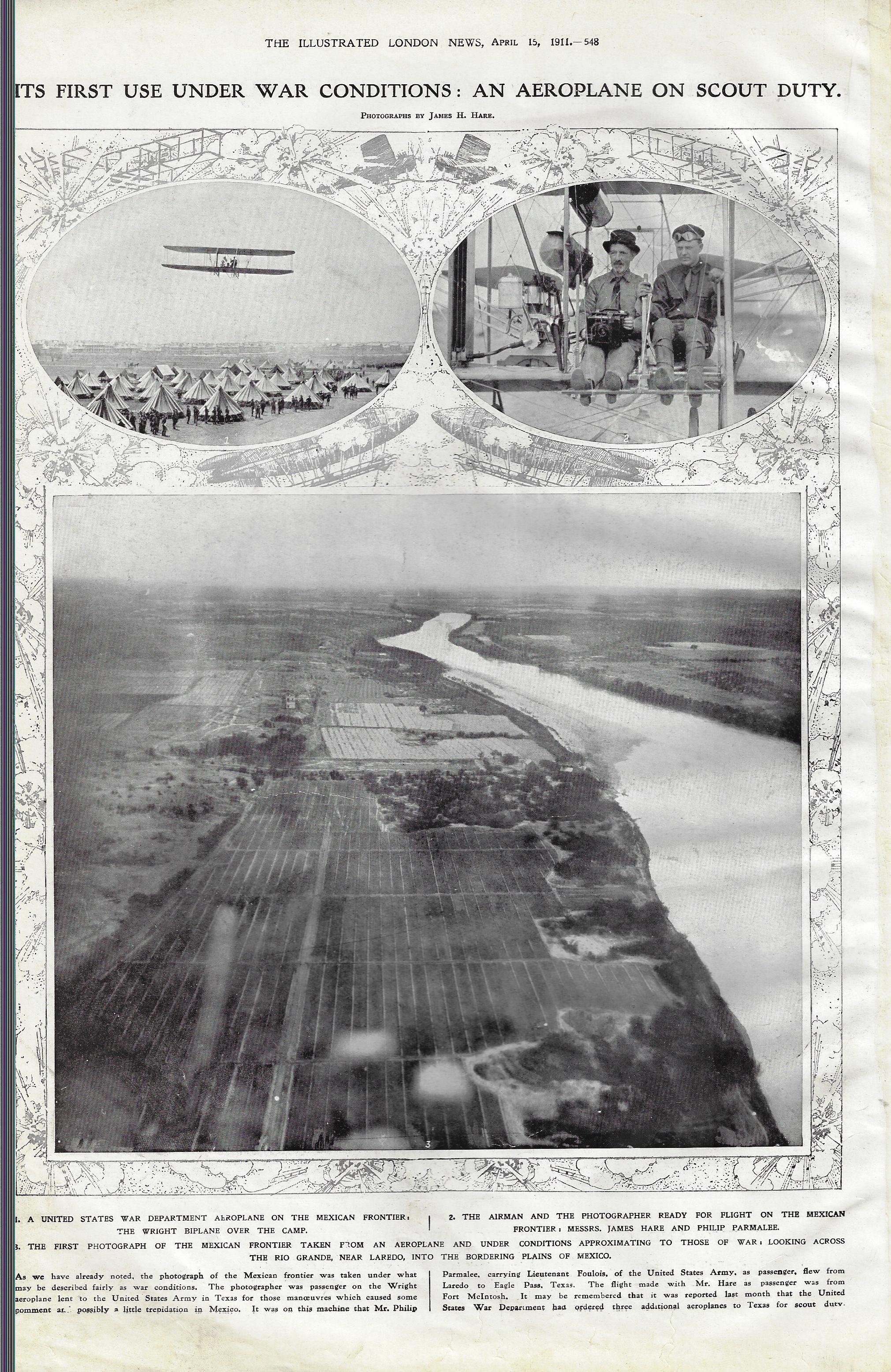
    I am not an historian of aviation, though the item I just found grazing through a volume of the Illustrated London News for 1911 may be one of the asterixed poor Roger Maris footnotes in the history of military flight. The title of the series of pictures–“Its First Use Under War Conditions–an Aeroplane on Scout Duty” appeared in the ILN issue for 15 April, and referred to flights being made over the U.S./Mexican border during the Border War of 1910-1919, (Poncho Villa, Mexican Revolution, J.J. Pershing, and all that). The writer didn’t want to go so far as to state that these were actual war conditions in which the plane was being flown, remarking that they were “Taken under what might be described fairly as war conditions”. So, it seems as though the title is accurate in a restricted way.

    I am not sure when the first use of a plane was as a scout vehicle during wartime, though certainly the first use of an airplane to deliver a bomb in a battle during actual wartime occurred seven months later. “During fighting in November 1911 between Italy and forces loyal to the Turkish, Ottoman Empire, Lieutenant Giulio Gavotti wrote in a letter to his father: ‘Today I have decided to try to throw bombs from the aeroplane. ‘It is the first time that we will try this and if I succeed, I will be really pleased to be the first person to do it.’ “–Alan Johnston, BBC News, “Libya 1911: How an Italian pilot began the air war era”

    And indeed he did, and he was.

    ILN 1911 airplane war use

    ·Posted by :

    ·in:

    —
  • A Utopia in a Couple of Thousand Words, or Fewer (1893)

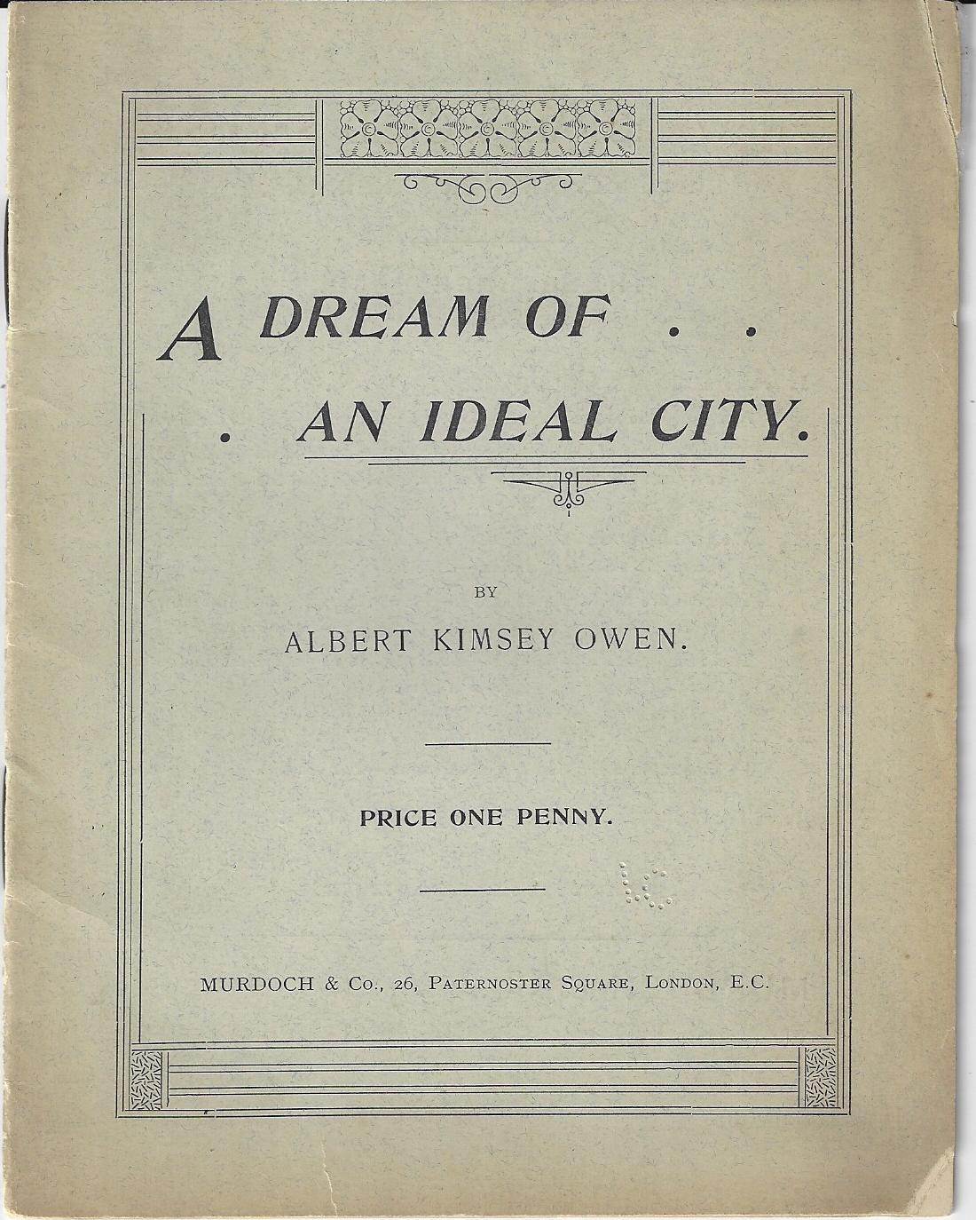
     Book UtopianWritten in 1893, A Dream of an Ideal City is a very short treatise on a very long topic. The author, Albert Kimsey 
    Owen1, was a civil engineer (when there weren't many, according to US census reports) and a dreamer,
    part of which was a vision of a Utopian community situated in Mexico on the Gulf of California.
    There is so much about this planned community that is suggested in these few short pages that it is
    hard to summarize, because the text is mostly summary—so I think I'll just quote from it at length from the online
    copy at the Internet Archive. (And frankly sumamrizing a bouncing summary like this that is nothing but very long
    sentences and very many commas would just be too annoying a process for the end result. Reading the quotes though
    is perfectly fine if not tiring.)

    Overall View, Placement and Work:

    • “I love to dream of the citizens in a large community being associated, for life’s work, in one great firm incorporated to build, by and for themselves, the best appointed, the most beautiful, and the greatest city on earth; a park residence, a city in which the metropolis, with its facilities,
      entertainments and cultures, and the country, with its green fields, hedgerows and shades;
      a seaside resort, where surf-bathing, fishing and yachting will be only an hour’s remove from the places
      of industry, commerce and home;
      every citizen may have self-appointed employments, a sufficiency of
      this world’s goods, and an elegant leisure in which to enjoy life with all its well-appointed pleasures and
      modern advantages.”

    Here’s another section of a sentence that seems almost to never end in spite of it varied contents:

    • “…the municipality being laid out, built up and managed with order, system and authority from the
      start to the finish — of the plan being studied, fixed and approved, before a step has been taken to execute
      the work — of the construstion of stone piers, the laying of giant sea-walls fronting the Straits of Joshua
      and Ohuira Bay, the digging of canals to extend and improve the water front, the planting of palms- along
      these great quays, the eredting of model blocks, the opening and shading of thoroughfares, the establishing
      and perfecting of varied and useful home industries upon areas reserved especially for them, and the
      building and furnishing for each resident family of a handsome and permanent home from the centre,
      solidly and rapidly to the four quarters of the compass, over one of the fairest plains, and in one of the
      most health-giving localities ever selected for the dwelling-place of mankind.”
  • Interesting Dust-Covered Numbers–Apartments in NYC in 1933

    JF Ptak Science Books   Post 2749

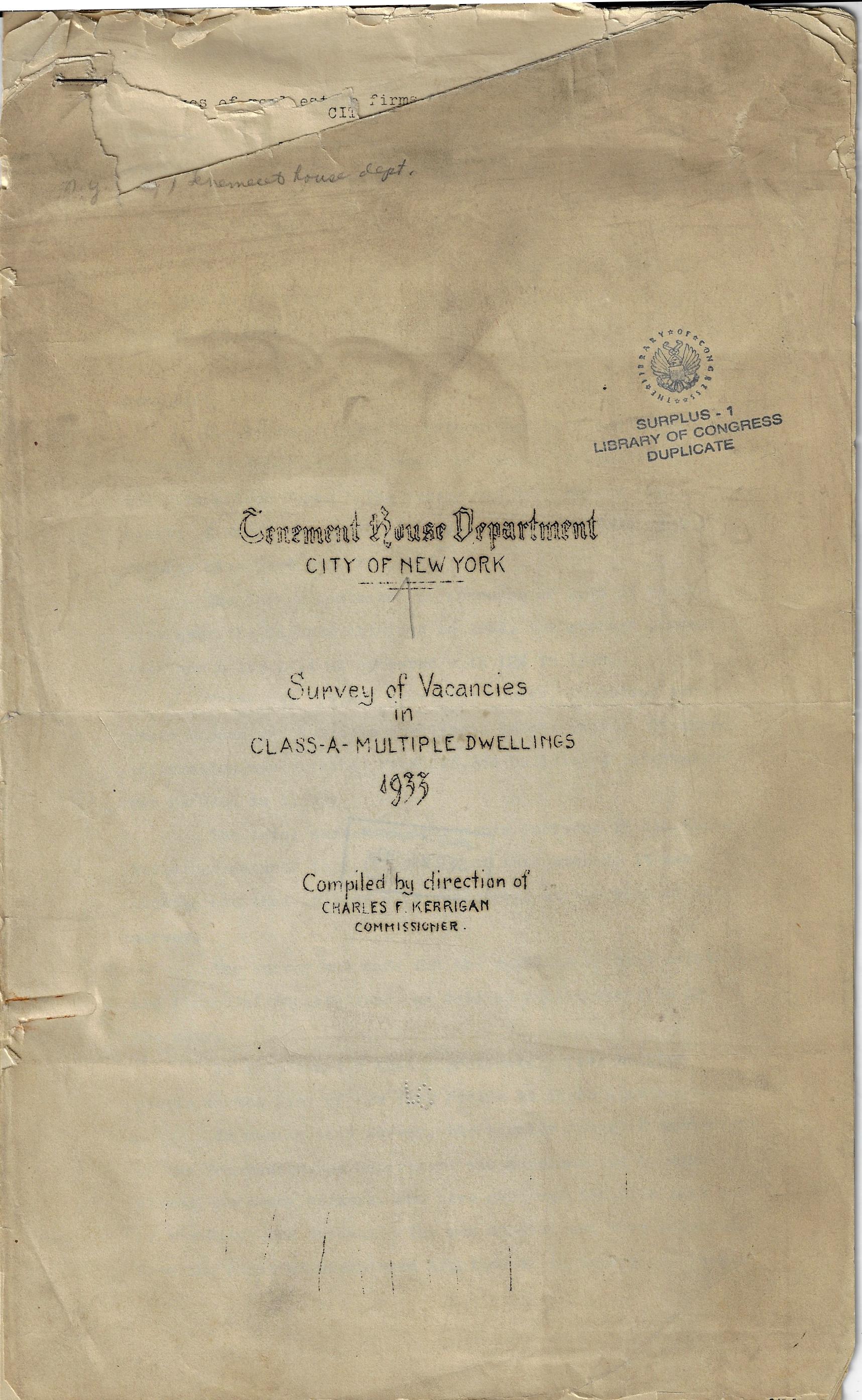
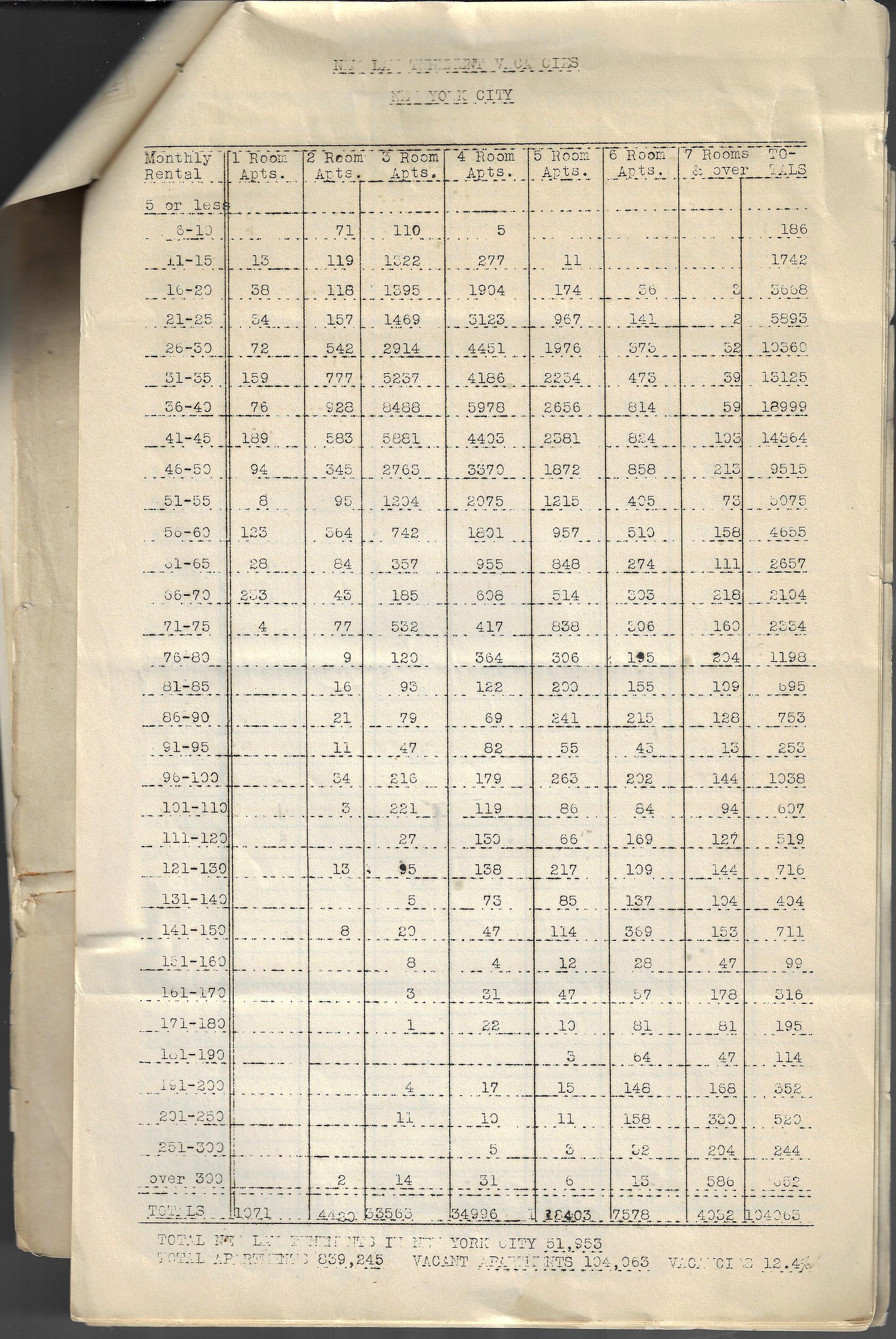
    NYC apartment rents 1933 coverI know that there must be someone out there in Webtubiana desperately looking for this in a way in which they didn’t know they (a) needed it at all and (b) didn’t know that that unknown need was desperate. And so here it is: New York City apartment vacancies in 1933. There is a tale being told here, in NYC, in the fourth year or so of the Depression and the first year of FDR, about what could be afforded and how much that all was. The list is found in eight pages of Tenement House Department, City of New York: Survey of Vacancies in Class-A-Multiple Dwellings, compiled by the Commissioner Charles F. Kerrigan, and dated in the text “May 11, 1933”.  It is a mimeographed production with a done-at-the-office quality to it, the typewriter having a problem with “9” and “0” and “O” as they tended to be filled in with ink. 

    I know this sounds as brittle as ice on an ego, but once you get past the dust, there is definitely a story being told, if you looked for it.

    At the very least this document will tell you what the rent was like on apartments from 1-7 rooms (elevator and non-elevator buildings), which means that if you consult the ever-useful Bureau of Labor Statistics inflation calculator you can at least establish a common denominator for value interpretation into current dollars. There are 33 (!) price classifications for monthly rental, ranging from $5 (or less) to “over $300”.  So, using the BLS formula $1 in 1933 is worth about $19.21 in 2018 (or for the sake of convenience let’s say 1:20). So the cheapest monthly rent in 1933 for a vacant 1-room apartment in 1933 was $100…except there weren’t any available. The next step up was $6-10, and using the upper end at $300/month there were only 13 1-rooms vacant. The most-available of these price ranges was 189 1-rooms in the $31-$35 range, or about $700 vacant. There was nothing vacant over $75/month in a total of 1071 vacancies. 

    The most commonly-vacant category was in the $26-$40/mo (or $800/month) 3 room apartments, where there were 8,488 apartments available in the 33,563 vacancies. 

    It turns out that of the 839,245  “total apartments” in NYC there were 194,963 vacancies for a rate of 12.4%. Nowadays the vacancy rate for Manhattan hit a high of 2.6% in 2017 and the average studio apartment rented for about $3k (or $156 in 1933 dollars, which would have put you in the upper tier apartment dwellers back then). 

    Different times.

    There’s more, and if anyone needs it they can let me know and I’ll provide what I can. Right now I’m dead-up against my THX-1138 time limit of 30-minutes/post, so this one ends now. 

    NYC apartment rents 1933


    ·Posted by :

    ·in:

  • Data Visualization of Comparative Naval Strengths, 1929

    JF Ptak Science Books  Quick Post

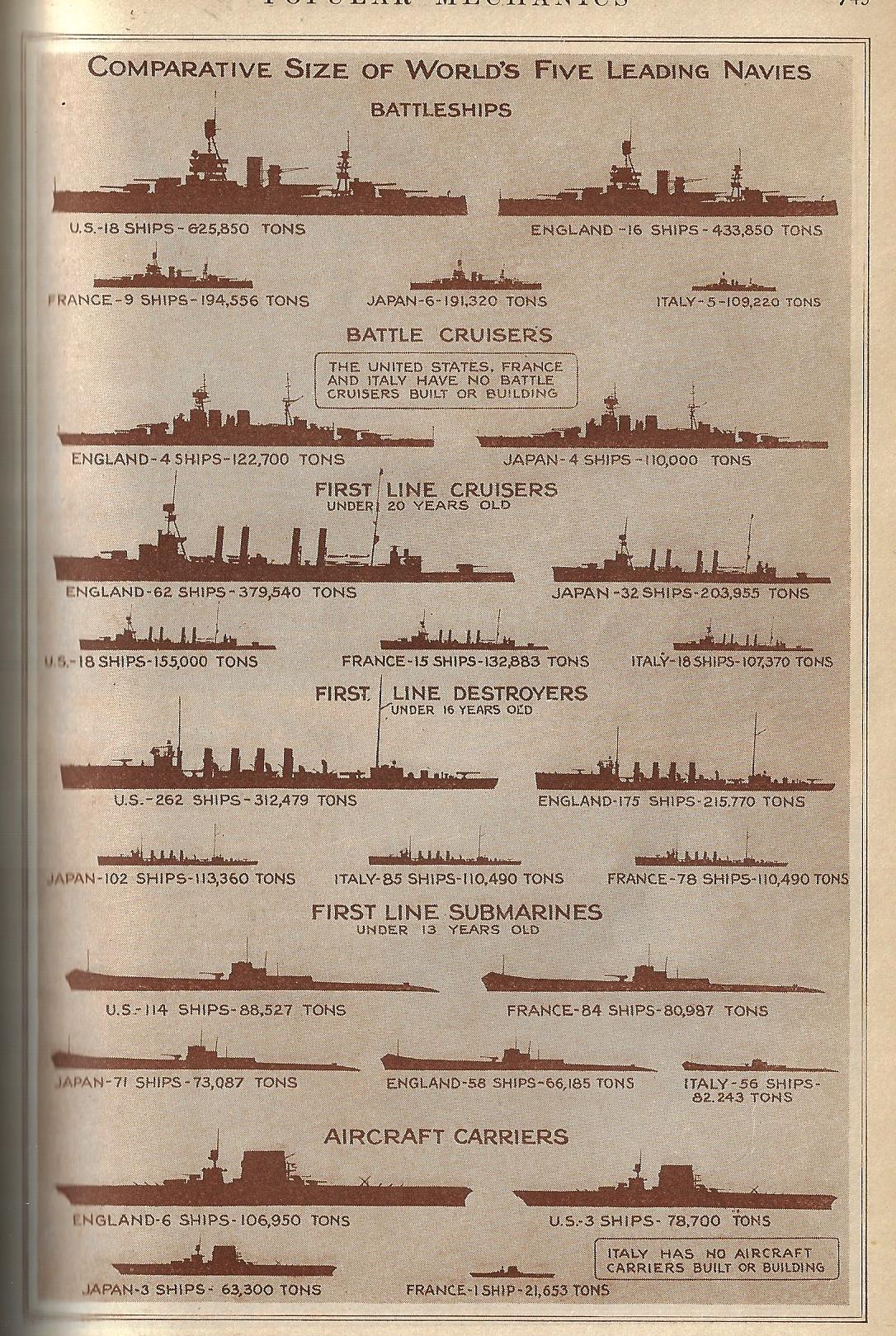
    There are many more complex, complicated, and data-rich displays like this one presented on this blog (just access the “Display of Quantitative Info” section), but there is a certain attraction with this simple-ish one. It is the design of W.R. Robinson–an artist with a fine touch, which is on display here more for the employment of empty space than lines–and gets across the information pretty easily and quickly. In any event, here it is, displaying the relative strengths of the world’s navies ten years after the end of WWI, which at that point was still the great War, “World War I” waiting to be invented in another ten years when there was a needed distinction between that world war and the newest world war.  

    Pop Mech 1929 dataviz navy strength

    [Image source: Popular Mechanics, June, 1929.]

Recent Posts

Archives

Categories