A Daily History of Holes, Dots, Lines, Science, History, Math, Physics, Art, the Unintentional Absurd, Architecture, Maps, Data Visualization, Blank and Missing Things, and so on. |1.6 million words, 7500 images, 4.9 million hits| Press & appearances in The Times, Le Figaro, Mensa, The Economist, The Guardian, Discovery News, Slate, Le Monde, Sci American Blogs, Le Pont, and many other places… 5000+ total posts since 2008.

Category: Cross-Sections

  • A New Category: Techno-Naive Art (1924)

    JF Ptak Science Books  Quick Post  Overall Post 5131
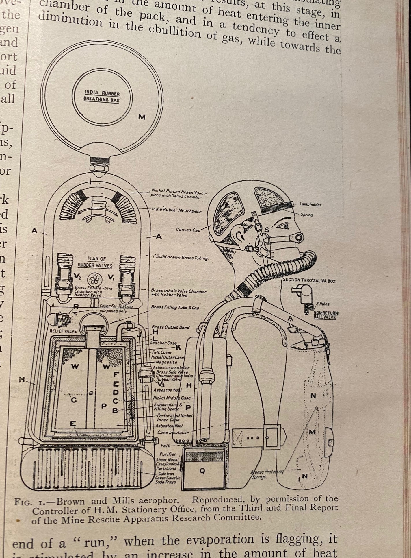
    IMG_4792What a fantastic drawing! I don’t mean to diminish this invention at all, though I must say that I was attracted to the article for the very 1950’s comic book naive and technical (Techno-Naive!) quality of the illustration.  Maybe it is just the subject’s profile that has thrown me into this new spin. 

    That said, this invention was conceived for the rescue of miners and for oxygen-deprived mining, and is known as the Brown & Mills Aerophor, which was “a liquid air respirator for mine work and rescue”.  I found this in the pages of Nature, 11 October 1924, p. 543.

    Brown and Mills evidently worked and improved an earlier idea and design by Col. Cuthbert Blackett (1910), which this citation from Wikipedia: “The Blackett’s Aerophor is a nitrox semi-closed-circuit rebreather with liquid gas storage made in England from 1910 onwards for use in mine rescue and other industrial uses. It was used until the 1950s. “Aerophor” is from Greek αεροφορος = “air-carrier”. Its breathing bag was on the chest, of rubber, in a strong leather case. The other parts were in a backpack. It had two corrugated breathing tubes coming out of the backpack. Its duration on a fill was 2 hours. “


  • The Underground Vaults of Harper & Brothers, 1855

    JF Ptak Science Books  Quick Post

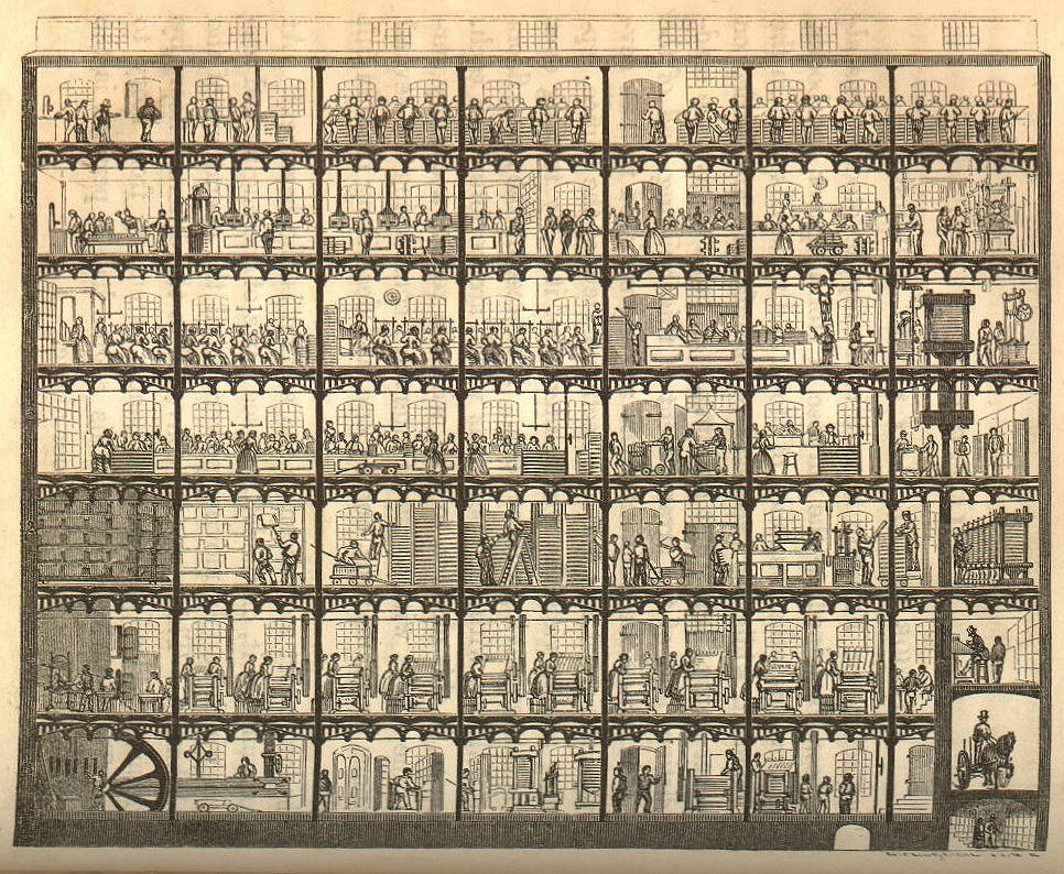
    I found this fantastic cross-section of the Harper & Brothers publishing house in Jacob Abbott’s The Harper Establishment, or, How the Story Books are Made, published of course and thankfully by Harper in 1855, and found in its entirety here.

    Harper & Bros memory vaults

    The whole of the enterprise is explained on pp 43-49.  I’d really like to return to this image at some point, because there are more detailed engravings in the book to match every section of the building, and to me it looks like this image could be turned into a 19th Century Printing and Publishing Board Game.

    What I was interested in right now was the box on the extreme bottom-right, which turns out to be The Vaults–this is the central memory core of this publisher, a 200-foot-long, 8×8′ corridor lined with the original plates for all of the publications of the firm.  The plates for their single-volume version of Herman Melville’s Moby-Dick would’ve been put down there just a few years ago. 

    “The plates are stored in subterranean vaults built under the streets that surround the building. The entrance to these vaults has already been shown in the sectional view of the Cliff Street building, on page 42. (A more enlarged view is shown on the preceding page.) The vaults extend under ground for two hundred feet in length, and in dimensions are eight feet wide by eight feet high. They are shelved on both sides, and the shelves are loaded with plates–stereotype or electrotype–representing all the works published in the establishment. There is one plate for every page of every one of the many hundreds of volumes which the house publishes, making from fifty to seventy tons in all.”

    “When a new edition of any book is required, the plates are brought out from these vaults and put upon the presses. When the work is finished, they are taken back again to the vaults.”

    ·Posted by :

    ·in:


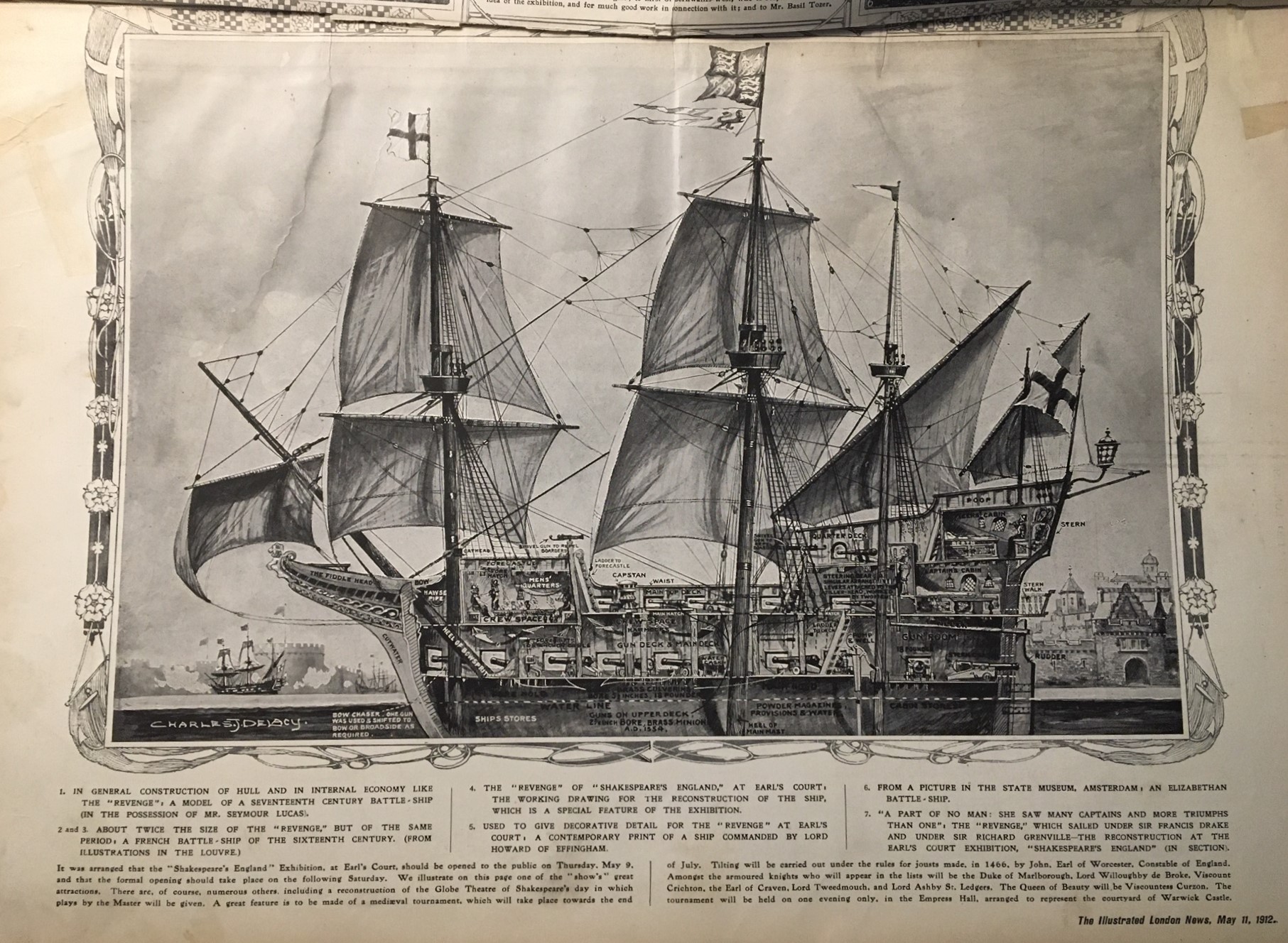
  • Great Cross Section: HMS Revenge of 1577 (1912)

    JF Ptak Science Books  Quick Post

    ILN 1912 Cutaway cross section REVENGE _2_

    [Image source: Illustrated London News, 11 May, 1912.]

    I’ve made dozens of posts on this site on cross sections, exploded views, and cutaways–today’s installment is another of the high-artistic variety and depicts the first (of fourteen?) of the HMS Revenge ships, laid down in 1577. 

    [Detail below.]

    “On July 20 the day on which the London Devonians celebrated the 324th anniversary the defeat of the Spanish Armada the King and Queen paid a visit to the England Exhibition at Earl’s Court. Amongst other things they inspected the model of the Revenge famous not only as the one of the one and the fifty three whose great fight Tennyson tells so dramatically in The Revenge, A Ballad of the Fleet but as the flag ship of Drake beyond doubt the greatest man who ever set foot aboard her. The ship as reconstructed at Earl’s Court is 104 feet long from stem to stern with a height of 127 feet from water line to top of mainmast and a breadth of beam of 28 feet…” Illustrated London News, 10 August 1912.


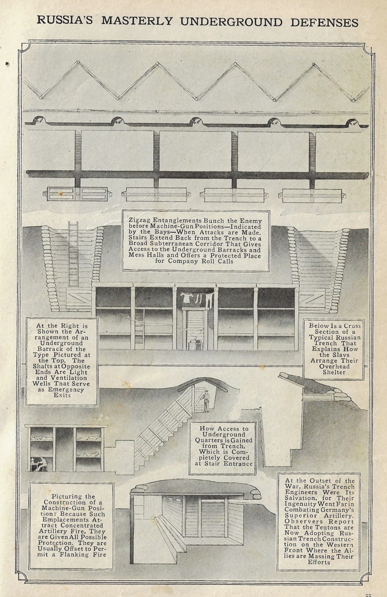
  • Russian Trench Cross-Sections, 1917

    JF Ptak Science Books  Quick Post

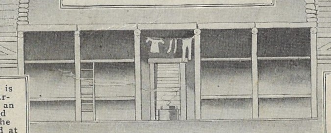
    I’ve made a number of posts to this blog on trenches/trench life (findable by entering the search term in the google box at right) and I believe that I’ve not made one regarding Russian trenches, until today. This image (“Russia’s Masterly Underground Defenses”) appears in a news-of-the-world section of Popular Mechanics for July, 1917, and includes a number of very smart smaller cross sections of division of the works. The whole of it is headed by a plan of the works, followed by  several smaller works, including the central image which shows the great depth at which the sleep chambers are set. (I also enjoy the bit of free will by the illustrator to include some tiny laundry drying out in the barracks.) Its a lovely work of an uncommon visual.

    Pop Mech 1917 Russian trenches
    Pop Mech 1917 Russian trenches

    ·Posted by :

    ·in:

    —

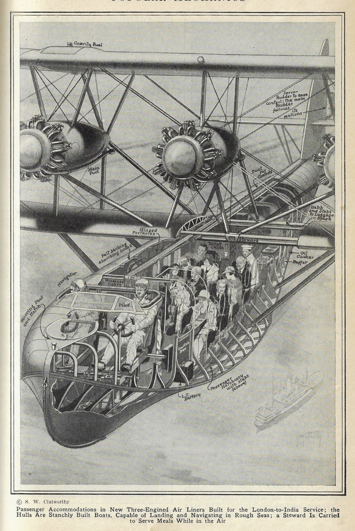
  • Flying to India from London at 93 mph (1928)

    JF Ptak Science Books  Quick Post

    These oblique cross-section and cutaways have been near-and-dear imagery for a long time, and I’ve probably made 50+ posts on this blog sharing them. This drawing is by S.W. Clatgworthy and appears in Popular Mechanics for March, 1928– it depicts the not-identified and brand-new “Short S.8 Calcutta”, which made its first flight the month before.  The airplane was designed for the Mediterranean leg of the London-India service of British Imperial Airways (1924-1939 when it merged into BOAC and then in 1974 became British Airways) and was the first stressed skinned metal hulled flying boat, and was constructed by Shorts1. Its three Bristol Jupiter engines pulled the aircraft along at about a 100 mph cruising speed, which no doubt made for an exciting and relatively fast (by 1928 standards) trip to the East.  The aircraft was pretty large for the day: 66′ long with a wingspan of 93′ and a height of 23′. It was probably noisy but relatively comfortable, the passengers being served food and drinks by a steward. Far less comfy were the pilot and navigator, who as you can see were in an open cockpit. 

    Pop Mech 1928 cross section airplane

    Notes:

    1. Shorts was the firm started by the Short brothers in Battersea in 1908 and which was the first aircraft manufacturing company to make production airplanes. 


    ·Posted by :

    ·in:

    —

  • “The Earth a Vast Bombshell” (1854)

    JF Ptak Science Books  Quick Post

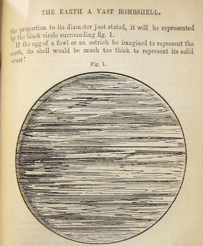
    What a great running title this is: “The Earth a vast bombshell”!  It appears in a section on earthquakes and volcanoes in a popular series by Dionysius Lardner’s The Museum of Science and Art (vols III & IV). Lardner reaches this conclusion after reasoning that if the increase in temperature of the earth increases as it seems to that at the dept of 40 miles the Earth would have a temperature of 40000, increasing 1 degree fir every fifty feet of depth, “or 1000 per mile”.  And so at these temperatures it must be so that most of the interior of the Earth would be “liquid fire” which “must extend to the very centre of the globe…”

    The accompanying picture shows a cross section of the Earth, “the thickness of its shell being in the proportion…will be represented by a black line”, everything else being the lake of fire. 

    “It is no rhetorical exaggeration, then, to affirm that the globe we live on is a stupendous by very thin bombshell charged with liquid fire!”

    Earth a vast bombshell 1854

    • “As cast into the lake of fire and brimstone, where the beast and the false prophet are, and shall be tormented day and night for ever and ever.” –Revelation 20:10
    • “Then Death and Hades were cast into the lake of fire.”—Revelation 20:10-14

    “Love is a burning thing, And it makes a fiery ring, Bound by wild desire, I fell in to a ring of fire.

    I fell in to a burning ring of fire, I went down, down, down

    And the flames went higher

    And it burns, burns, burns

    The ring of fire

    The ring of fire.”–Johnny Cash, “Ring of Fire”. 


    ·Posted by :

    ·in:


  • A Fine Engineering Effort: Constructing the Foundation for a New Building Under the Still-in-Use Building to be Replaced (1922)

    JF Ptak Science Books   Quick Post

    Here’s a very interesting engineering and building feat: placing the foundations for a new building to replace an older one while the older one was still (1) standing and (2) in use. The recipient of this effort was the McVickers Building in Chicago, a theater that opened in 1857 and came to it slow end in 1922. It looks like the last bit of currency was squeezed out of this old building, performances being given right to the very end while foundations for the new building were being constructed 24 hours a day. Int he world of cross sections this is a good one, and also pretty unusual. Also in the top left corner we see a photo of a caisson under construction–a shot I don’t see very often in my searches of old stuff.  

    Pop Mech 1922 Cross section theatre caissons

    Source: Popular Mechanics, February, 1922. 


  • An Episode in the History of Manure: “To barren ground with toyle large meanour add.”

    JF Ptak Science Books  Quick Post

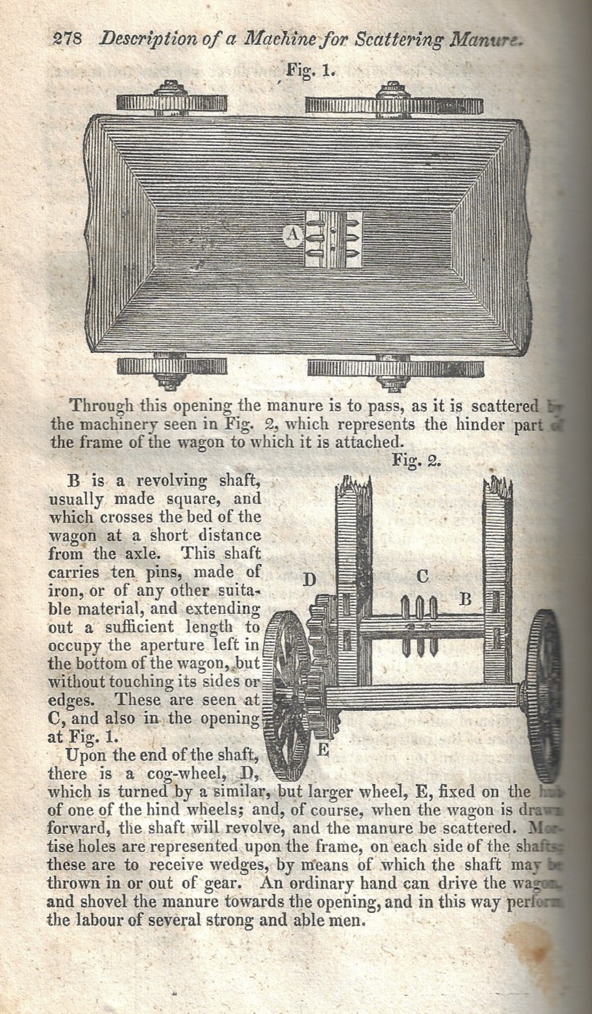
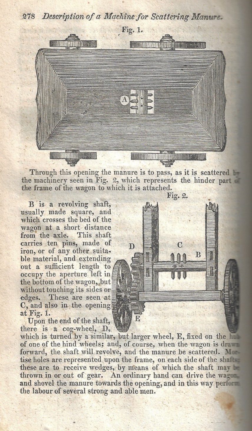
    Franklin Institute 1829 Manure spreaderOf the many things that can be said about manure you can’t say but can say about its chemical replacement is that it is made from fossil fuels and sucks good stuff from the soil and ultimately makes the farmland it is fertilizing unfarmable. That’s what popped into my head when I bumped into this woodcut of a manure spreader while farming something else in the 1829 volume of The Journal of the Franklin Institute. It’s a relatively simple improvement to a necessary and laborious job–adding the spreader made the application of manure far easier than have it slide through a jamable sluice in the bottom of a wagon, and certainly a lot easier and more thorough than spreading it by hand. 

    And just for the fun of it I checked out “manure” int he OED, where it makes appearances in English beginning in the mid 16th century, and for the hundreds of years the word has been around it has a complicated spelling history (manoure, maynor, maynure, menar, menor,  menore, meynor,  maner, meanor,  meanour, manure, mainure,  manier, manner, mayner,  meanure, menure; maner,  mannor,  mainer,  manna, manner, mannur, manor, manuer; manar, pre-maner, mannor, mannour,  mannur,  manuire, manure,  manour, mainer; U.S. regional (southern) manyo). Here are two examples of early usage that have some poetic sense to them:

    • 1664   J. Evelyn Sylva (1679) 10.   “To barren ground with toyle large meanour add.”
    • 1697   Dryden tr. Virgil Georgics ii, in tr. Virgil Wks. 85.   “In depth of Earth secure Thy cover’d Plants, and dung with hot Manure”.

    The term “Manure spreader” according to the OED comes into use around 1884, 55 years after this report–except of course this is called a manure “scatterer” which seems to imply less confidence than a “spreader:, though that may have come about due to the modesty of the inventor. 


  • Some Good Military Cross Sections from “Popular Mechanics”, 1943

    JF Ptak Science Books  Quick Post

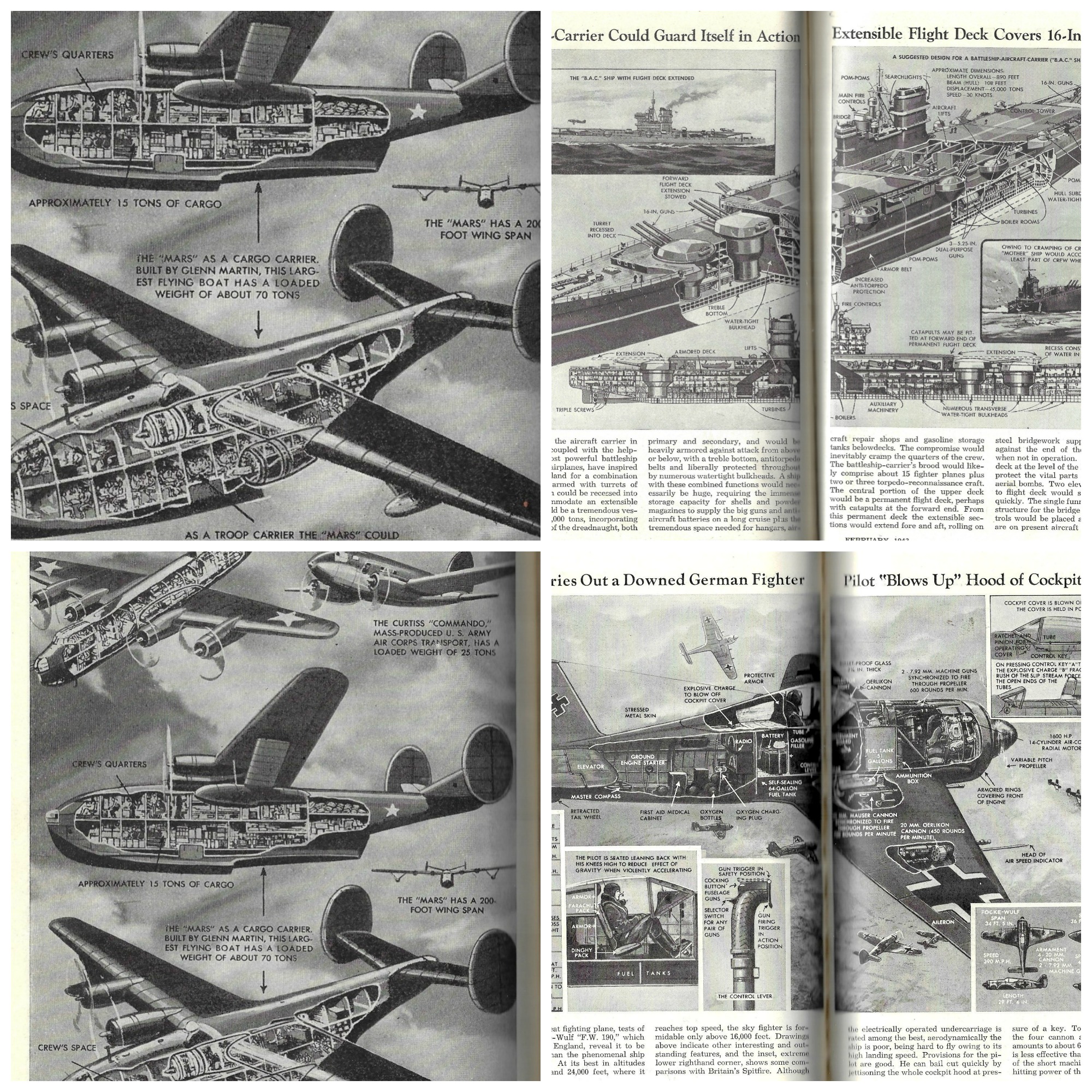
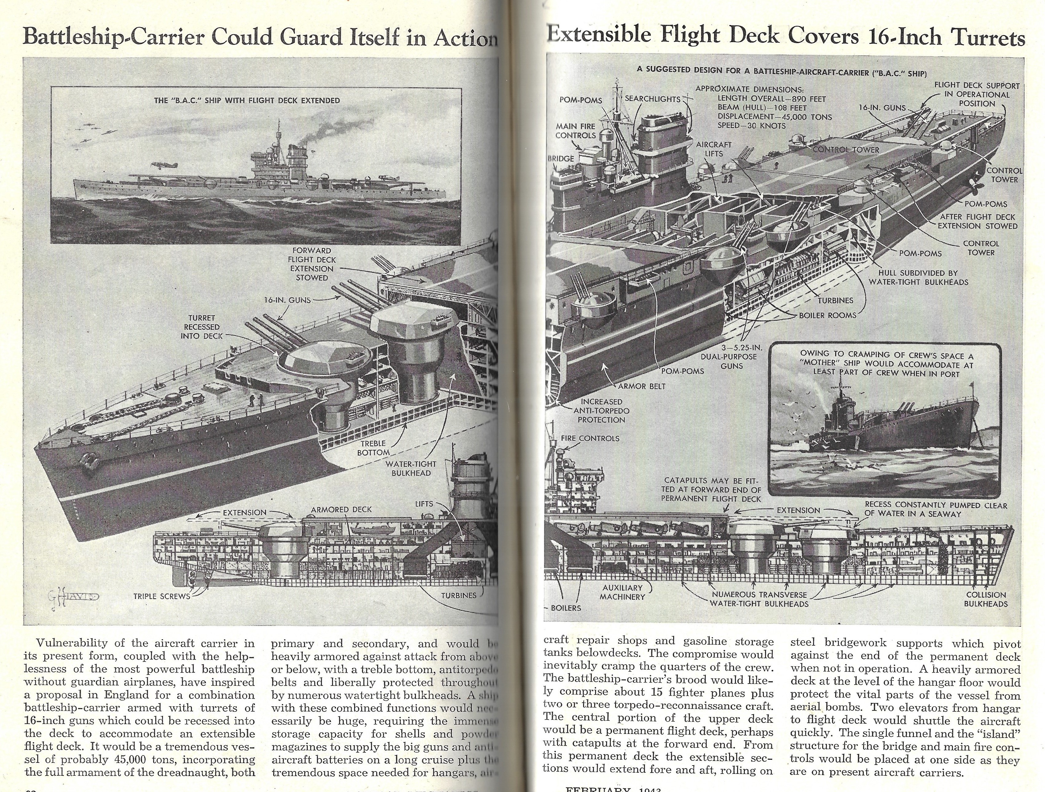
    Here are three fine cutaways from my favorite cutaway artist, George Davis. (He has appeared many times on this blog–just have a peek by entering his name in the Google search for the blog and you’ll have a number of hits.) These three appeared in a volume of Popular Mechanics for the first half of 1943 and feature comparisons for the cargo aircraft “Mars” (from Glenn Martin), a review of a captured F.W.-190, and a think-piece on a possible cruiser-carrier. 

    Pop Mech 1943 cross section collage

    Aha. Here’s an interesting dream of a supership dreamed by some Brit engineering dreamers in 1943–a cruiser-carrier, or Battleship-Aircraft-Carrier (“B.A.C.” as the article says). This was a monster with nine 16″ guns and a host of other armament and defences, plus a flight deck accommodating 15 fighter plans. Although this was an older idea it seems to have picked up steam following the Battle of Midway. 
    Pop Mech 1943 FW 190 Aviation


    ·Posted by :

    ·in:


  • Aircraft Cross Sections, WWII

    JF Ptak Science Books   Post 2781

    Aircraft Cross section Collage

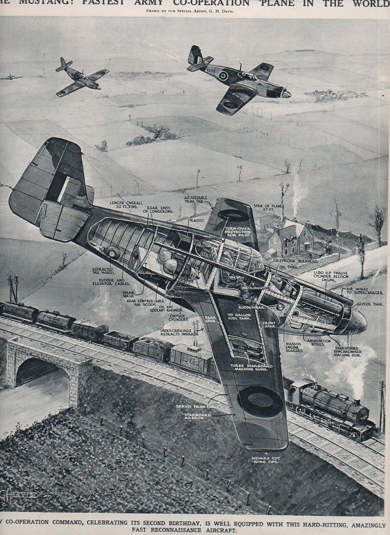
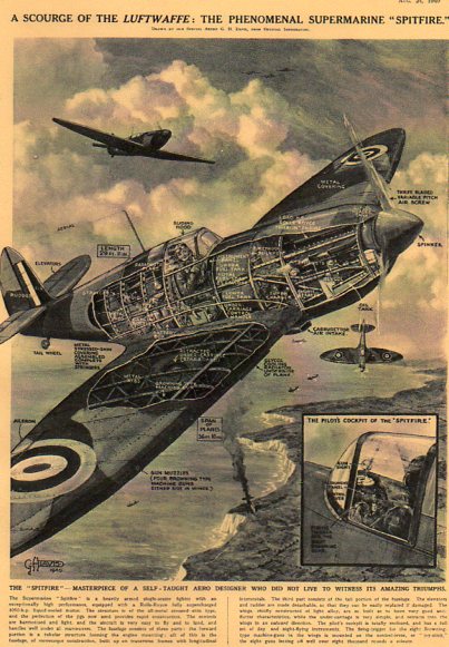
    I’m sharing some of the collection here of the published work of George.H. Davis (1881-1963), the prolific and vastly accomplished artist for The Illustrated London News. His work with that magazine for the forty or so years that I am familiar with is superb, and his great strengths can be found in rendering technical cross sections and infographics.  He had a great sense of design and a very fine hand, and so far as I can tell he displayed an excellent control of his subject, thousands and thousands of times (2,500 times, according to Mr. Davis).

    Here are some fabulous examples of technological cross sections of WWII aircraft by Davis–the drawings are just superb, and you can easily get lost in them, following the geography of engineering detail from one logical place to the next.

    Blohm u. Voss BV141 

    Aircraft cross section BV 141Surprise!  My first cross section isn’t one–I just couldn’t resist posting it, though. This aircraft is the Blohm u. Voss “BV 141″a very unusual-looking aircraft as it appeared in The Illustrated London News for 23 May 1942–it gives an excellent view of what the editors called “a lop-sided freak”.  Perhaps the editors of the ILN wanted to educate its readers on the plane since it was supposed to be widely employed on the Russian Front, though it looks like only 38 were ever built (and none survive today). Actually, the plane, designed by Dr. Richard Vogt (1894-1979),  was a high-flying three-seater  surveillance aircraft capable of 220 mph at 17,000 feet, powered by a single 1000 hp Bramo Fafnir 9-cylinder radial engine.  The idea for the design was to give the pilot and co-pilot a very wide field of view–and by this, I’m guessing that the field of view most affected and aided by this would be straight down. The rear gunner also had an enormous field of view. 

    As it turns out Vogt survived the war and spent his Golden Years in the U.S., seven of them (1960-1966) with Boeing to evaluate hydrofoils and vertical liftoff systems:  he had built other odd planes during his career, and carried them with them into near-retirement, making this sort of design his metier.

    “The Mustang–Fastest Army Co-operation in the World“, appearing in The Illustrated London News for 12 December 1942.  

    Aircraft cross section Mustang
     

     The Spitfire (perhaps the most beautiful-sounding aircraft of WWII):

    Aircraft cross section Spitfire


    ·Posted by :

    ·in:

    —