JF Ptak Science Books Post 2504
Leonard R. Bester was a marine architect and naval engineer who produced this very interesting document on his highly-stylized concepts for boat/ship design. The vessels are all certainly streamlined, and are long and narrow, and share the same “tubular” hull construction. He recorded them in these documents (below) which were sent by him to secure copyright protection to the U.S. copyright office, one copy of which was sent on to the Library of Congress. They were certainly produced on a very small production scale, perhaps only a few copies made, given what looks like their home-cooked flavor–in any event, they did not receive any circulation that I can find, and are not listed anywhere in WorldCat (which is a librarian’s tool for recording and documenting books) showing that nothing by Bester is listed in any contributing library worldwide.
Bester was definitely a working naval architect who possessed at least several patents1 who worked for the Todd Shipping Company (NYC) and who was listed by 1919 as a member of the Society of Naval Architects and Marine Engineers2 . The work looked interesting and intriguing to me, but is also in a field that I know basically nothing about, so I thought that given the possible interest in it to designers and engineers that I would at least enter the information about the work here in internettubewebland where it might be findable to someone interested in this sort of creative thinking.
- All of this is offered for sale at the blog bookstore, here.
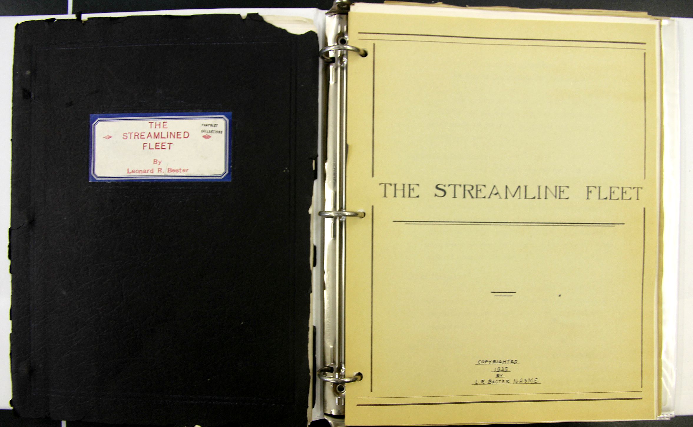
The work seems to be divided into two section, each section with three parts, and although not dated per se the title pages such as they are are copyrighted 1935 and 1936, with the later having a copyright/Library of Congress acquisitions stamp for 1936. The blueprints, on the other hand, date back as far as 1931, so there’s a bit of a mix. The work certainly is not passed 1936. Altogether there are 19 folding blueprints of boats, 36 pages of text, 12 photographs on three leaves, and several folding charts.
Section I: The Streamline Fleet (1935), divided into three sections.
Part I
- “Features and Advantages of the New Tubular Type Boat”, pp 3-6
- Tech illustrations in 12 figures, pp 7-9, followed by 6 leaves of 2 figur/leaf of various cross-sections
- “Design Features”, pp 10-14, with a folding plate: “Comparative plate of tubular type hull structure”, 13×18″
- “Main points of advantages of tubular design”, pp 15-17
- “Summary of the Streamline Tubular Boat”, pp 18-19
- “High Speed Yachts”, p. 22
- “Future of the Yachting Industry”, pp 23-26
- Conclusion, p. 27
Part II
- “Propulsion Machinery, Diesel Power”, pp 28-30, with 3 leaves of tables and 2 folding plates on the turbine
Part III
- “Navy Boats”, pp 31-36.
Part IV (folding plates)
- “High Speed tubular 50′ to 60′ streamline diesel cruiser, twin screw”, 11×17″, 1931
- High Speed tubular 54′ streamline diesel cruiser, twin screw”, 11×17″, 1931
- “Strealine 85′ Diesel Yacht”, 11×17″, 1932
- “Tubular steel 100′ streamline diesel commuting yacht, twin or triple screw” 11×17 inches (1931)
- Schematic: “tubular design showing strong and light construction”, 12×16″
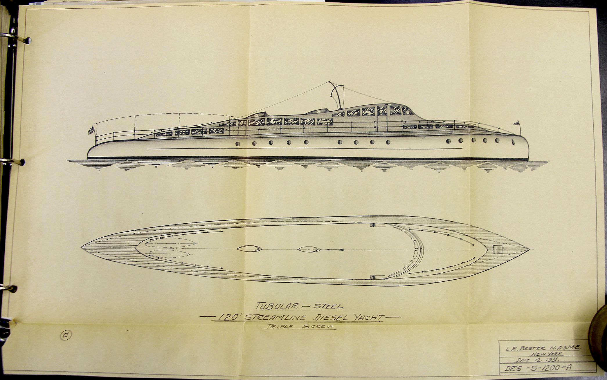
- “Tubular steel 120′ streamline diesel yacht, triple screw” 1931 11×17
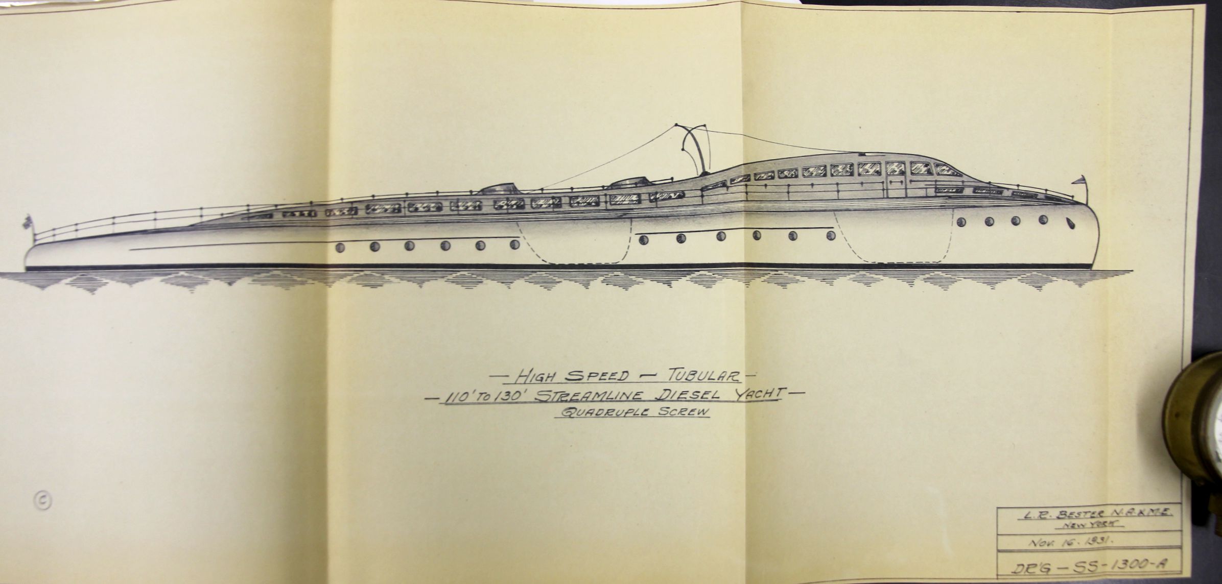
- “High Speed Turbine–Tubular–110 to 130′ Streamline Diesel Yacht, quadruple screw”, (1931) 11×24″
- “High Speed Turbine–Tubular–150′ Streamline Diesel Yacht, quadruple screw”, (1931) 11×24″
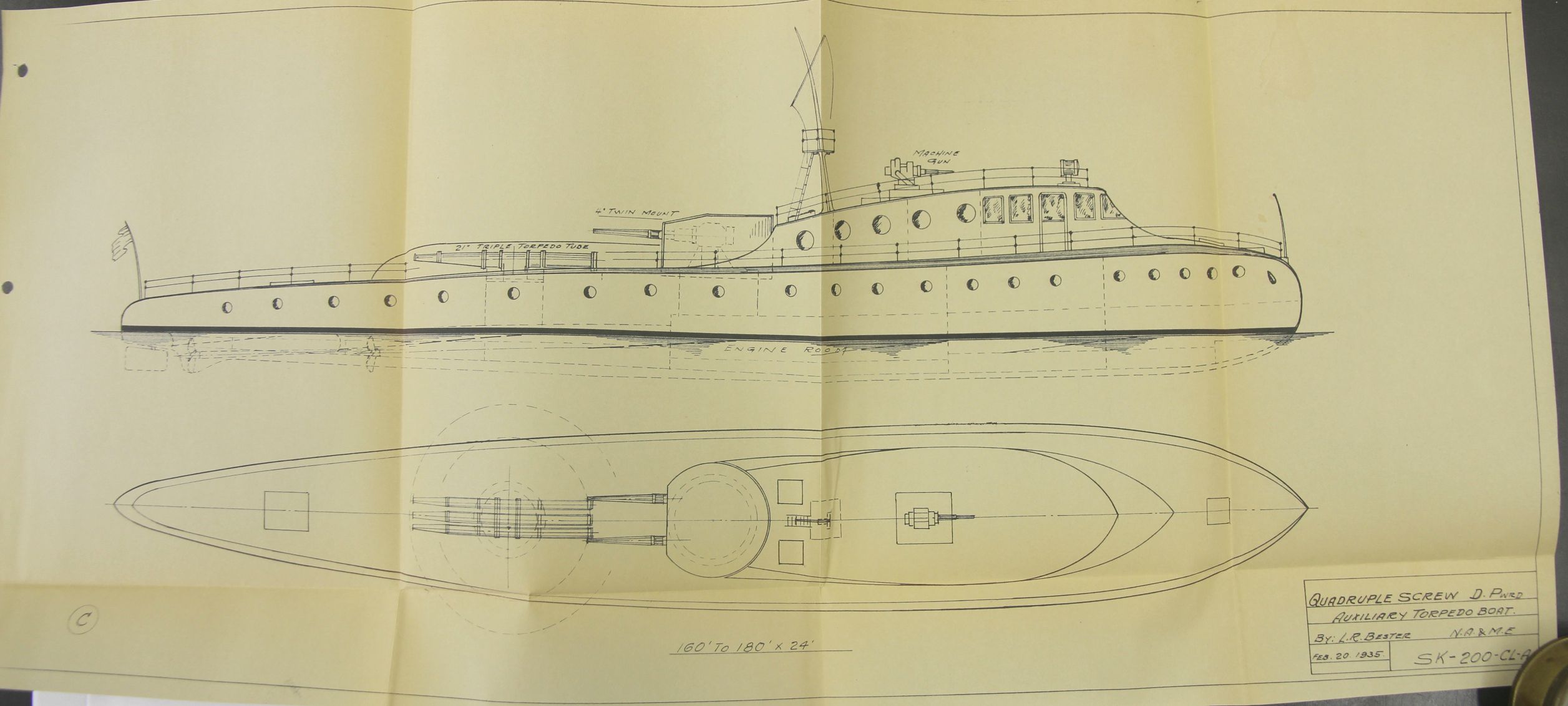
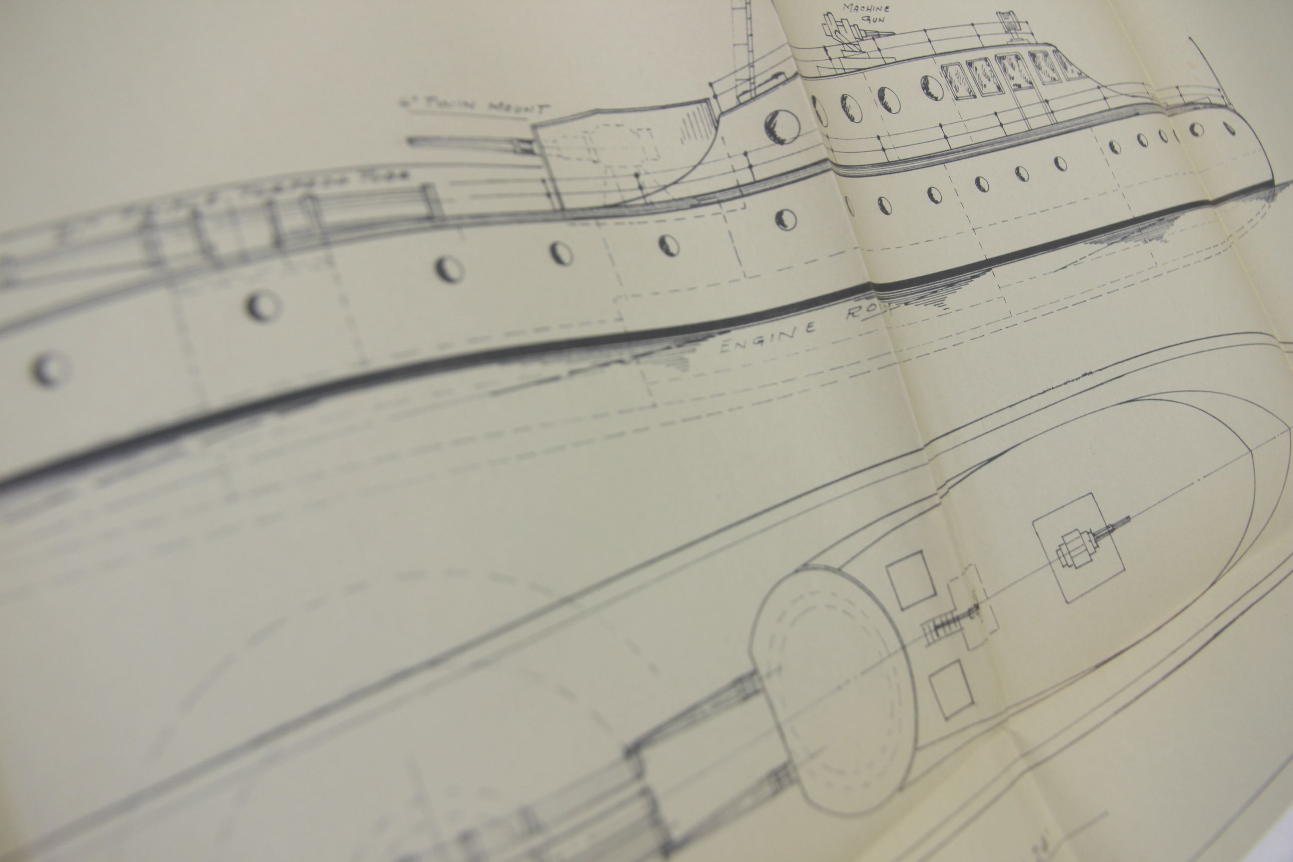
- “Quadruple screw diesel powered auxiliary torpedo boa”, 1935, 12×30″
Section II: Streamlined Tubular Hull Structure, Design, Layouts, and Interior Arrangement of Cruisers and Yachts
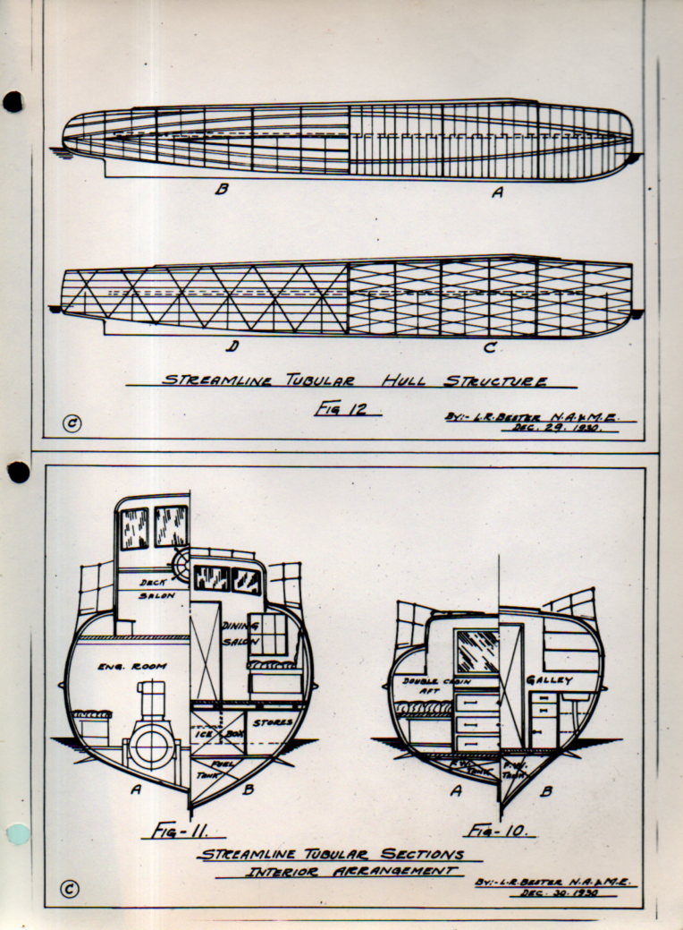
Part I contains seven folding plans and cross section blueprints of the design, includes the following sections:
- Streamlined Diesel Cruiser, 1936, 34×8′, 10×13 inches
- Streamlined Diesel Cruiser, 1936, 40×8′, 10×13 inches
- Streamlined Diesel Cruiser, 1936, 45×9′, 10×13 inches
- Streamlined Diesel Cruiser, 1936, 50×10′, 10×13 inches
- Streamlined Diesel Cruiser, 1936, 57×11′, 12×17 inches
- Streamlined tubular twin screw diesel commuting yacht, 23×16 inches
- another copy of Streamlined tubular twin screw diesel commuting yacht, 23×16 inches, though with different applications.
Part II contains 3 leaves, each with four original photographs each, with tissue guards. These are photos of scale models of Bester’s designs, though the dimensions are unfortunately not mentioned.
Part III concentrates on “express transportation yachts”, and contains five folding cross section blueprints:
- 65′ Express Transportation Yacht, drawing measuring 17×11 inches
- 65′ Express Transportation Yacht for 60 people, 19×11 inches
- 75′ Express Transportation Yacht for 75 people, 10×22″
- 85′ Express Transportation Yacht for 85 people, 10×23″
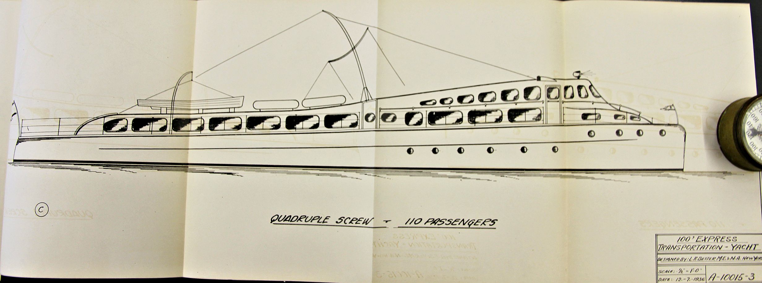
- 100′ Express Transportation Yacht for 110 people, 10×30″
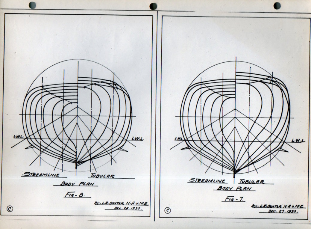
And some hull lines:
Notes:
1. Bester patented an approach to “tubular” hull construction (“Ship hull design”, filed in 1936 and patented in 1939, US2158214A), which seems reasonable to me (as a non-engineer). He describes it so: “It has been the practice in the making of steel vessels such as are commonly used, to provide framework consisting essentially of transverse web frames coupled with longitudinal members, whereby to give form and rigidity to the vessel. Even where the vessels were oval or cylindrical in general cross-section, the framing invariably embodied straight pieces. This type of construction had the considerable disadvantage that it was quite heavy and it was not possible to attain any great amount of saving in weight by variations in the arrangement and size of the several frame members. It was also impossible in such construction to reduce the labor cost in the building there of and also to reduce the cost of propulsion or materially increase the speed of the vessel without overstraining the hull structure.” Source: Google Patents, http://www.google.com/patents/US2158214
2. Proceedings of the Society of Naval Architects and Marine Engineers, volume 25, 1918, listing of the Society’s leadership and membership.