A Daily History of Holes, Dots, Lines, Science, History, Math, Physics, Art, the Unintentional Absurd, Architecture, Maps, Data Visualization, Blank and Missing Things, and so on. |1.6 million words, 7500 images, 4.9 million hits| Press & appearances in The Times, Le Figaro, Mensa, The Economist, The Guardian, Discovery News, Slate, Le Monde, Sci American Blogs, Le Pont, and many other places… 5000+ total posts since 2008.

Category: Cross-Sections

  • Standardizing Precision and Beautiful Technical Prints: Ramsden’s Dividing Engines

    JF Ptak Science Books   Post 1452.223221 and a quarter
      Ramsden386

    I like the idea of having something called a Dividing Engine–perhaps it would divide seeds, or complex problems, or simple problems, or perhaps it would divide division. 

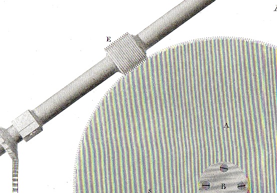
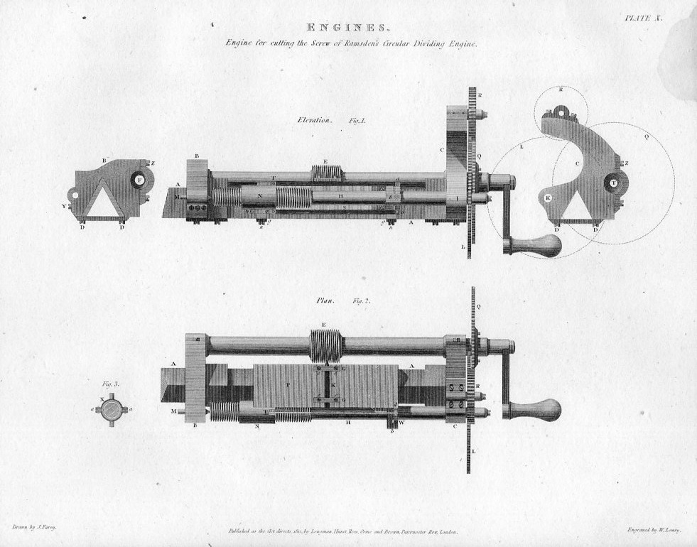
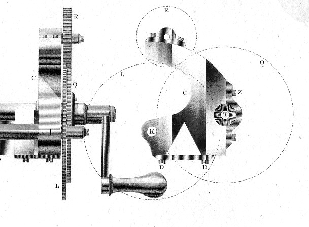
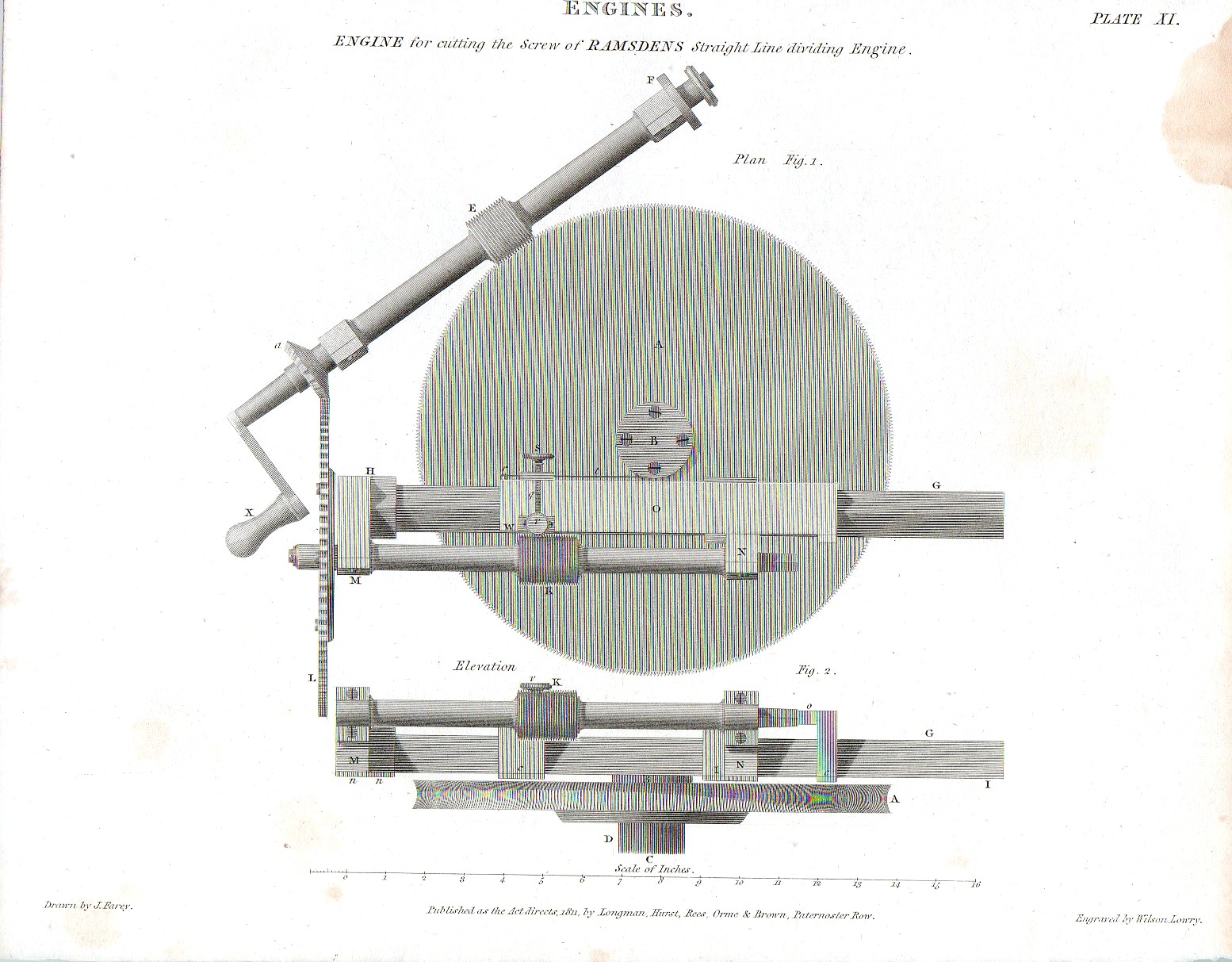
    What it really refers to here is a precision tool that whose effects were extremely wide felt but about which we don’t really hear about today.  This is the dividing engine of Jesse Ramsden,and Englishman who invented a circular instrument that would incise precise values on precision instruments like surveying compasses, delineate the linear and circular scales of measuring instruments used in astronomy and navigation,   Before Ramsden, the engraved marks on instruments would have been made by each individual manufacturer, each of those depending on marks that they made in the past, generations of such things in a line, over and over, a quite individualized effort, necessarily dependent upon the precision of each manufacturer. In 1777 Ramsden produced an instrument1 of exception precision that was correct and fine and dependable2. [The image above was found in Abraham Rees’ monumental Encyclopedic Dictionary…, and is entitled “Engine for cutting the screw of Ramsden’s Circular Dividing Engine” and was published in 1814.  Below is a detail of the plan for the winding of the gear works. In order for his machine to work at such a high degree of accuracy the component parts must also have been of a very high calibre–to that end Ramsden developed what is essentially the modern screw cutting lathe from which he manufactured the gear works for his Straight and Circular Dividing Engines.3]
    Ramsden387
    And then there was the “Engine for cutting the Screw of Ramsden’s Straight Line Dividing Engine”, which is an absolutely gorgeous piece of drawing.  A person could crawl all over this image in varying degrees of microscopic inspection and find all sorts of beautiful internal images, a large example appears here:
    Ramsden388

    And its fantastic detail:

    Ramsden389

    Basically though Ramsden’s inventions were key additions to the developing scientific technologies of the Industrial Revolution, integral improvements necessary for integral improvements. 

    Notes:

    1.  He published a Description of an Engine for dividing Mathematical Instruments in 1777.

    2. “The dividing engine was simple to operate. The instrument being divided was fixed to a large wheel on top of the engine. When the treadle was pressed, the wheel and the instrument were turned through a fixed angle. Then with the right hand, a cutting tool guided by a system of swinging links was used to mark the instrument scale. The process was repeated until the complete scale had been divided. Although this was many times faster than hand-dividing, it was backbreaking work having to lean over the engine to work on a small instrument.”-“Dividing Engine.” Smithsonian National Museum of American History. americanhistory.si.edu/collections/navigation/object.cfm?recordnumber=694508

    3. From WIki–“The first truly modern screw-cutting lathe was likely constructed by Jesse Ramsden in 1775. He appears to have been the first person to put a leadscrew into actual use (although, as Leonardo’s drawings show, he was not the first person ever to think of the idea), and he was the first to use diamond-tipped cutting tools.[2] His device also included a slide rest and change gear mechanism. These form the elements of a modern (non-CNC) lathe and are in use to this day. Ramsden was able to use his first screw-cutting lathe to make even more accurate lathes. With these, he was able to make an exceptionally accurate dividing engine and in turn, some of the finest astronomical, surveying, and navigational instruments of the 18th century.
  • The Mysteries Offered of Images out of Context

    JF Ptak Science Books   Post 1403

    “Certainly the most novel, if not the most successful, enterprise that New York has seen for many a day is the pneumatic tunnel under Broadway. A myth, or a humbug, it has hitherto been called by everybody who has been excluded from its interior; but hereafter the incredulous public can have the opportunity of examining the undertaking and judging of its merits.”  —The New York Times, on the opening of the pneumatic tunnel, September 1870.

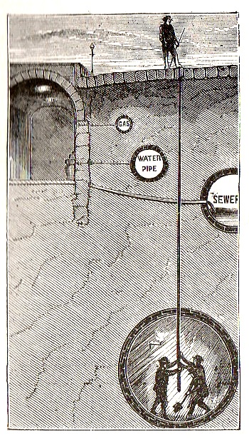
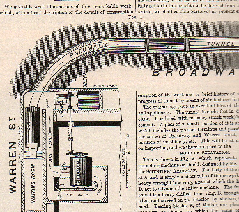
    These unusual images are all only so if they are removed from their context, taken from their stories, their explanations lost.  But the fact of the matter is simple–they show cross sections of some construction elements of “the pneumatic tunnel under Broadway, N.Y.C.” as it appeared in the Scientific American for 5 March 1870.  It was an experimental line, and did not really deserve the description received from the Times. The idea for an underground such as this was the brainchild of Alfred Ely Beach, and was basically a single-train, single-station, one-block system established for demonstration purposes, and was kept in operation from 1870 to 1873.  Technology overtook Beach’s idea of pneumatic propulsion with the development of electric trains, making the forced-air idea obsolete in short order.

    The images, without explanation, their purpose is well hidden.

    The first example simply depicts the way in which the progress of the tunnel was measured and mapped.  The two men underground sent up a series of pipes to the surface, under the very paving stone of Broadway, where a surveyor would make the spot where the pipes met the surface.  (We are told that this work was done at night, when the streets were empty.)  Any number of stories could be made of this image–all stretching beyond its intended purpose.

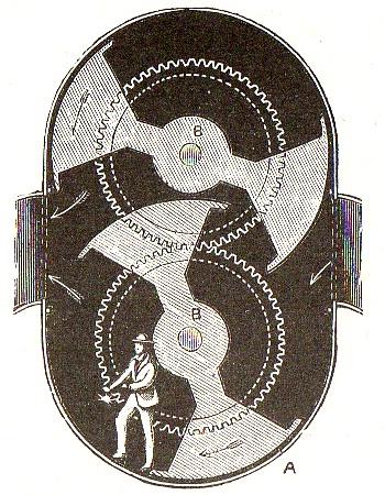
    Underground man224 This machine below could be virtually anything in the mind of anyone, except of course for its real purpose, which was to power the train.  It is a cross section of the apparatus, showing its two massive fans with a figure of a man added to show scale. 

    Underground man225

    “The power transfer is one of the most simple things imaginable. Air is forced into the tunnel by a gigantic blowing engine made by P. H. & F. M. Roots, of Connersville, Ind., a section of which is shown in Fig. 7. [missing] This blower is actuated by a steam engine of 100-horse power, and is calculated to deliver when worked at maximum speed, a volume of 100,000 cubic feet of air per minute. A pressure of one fourth of one pound to the square inch would be an aggregate of three-fourths of a tun on the end of the car, far more than required for propulsion.”

    Underground man226


  • Engineering Art: Cross Sections of the HMS Olympic (1909) and Mauretania (1906)

    JF Ptak Science Books  Post 1382

    “...And a Gymnasium.”

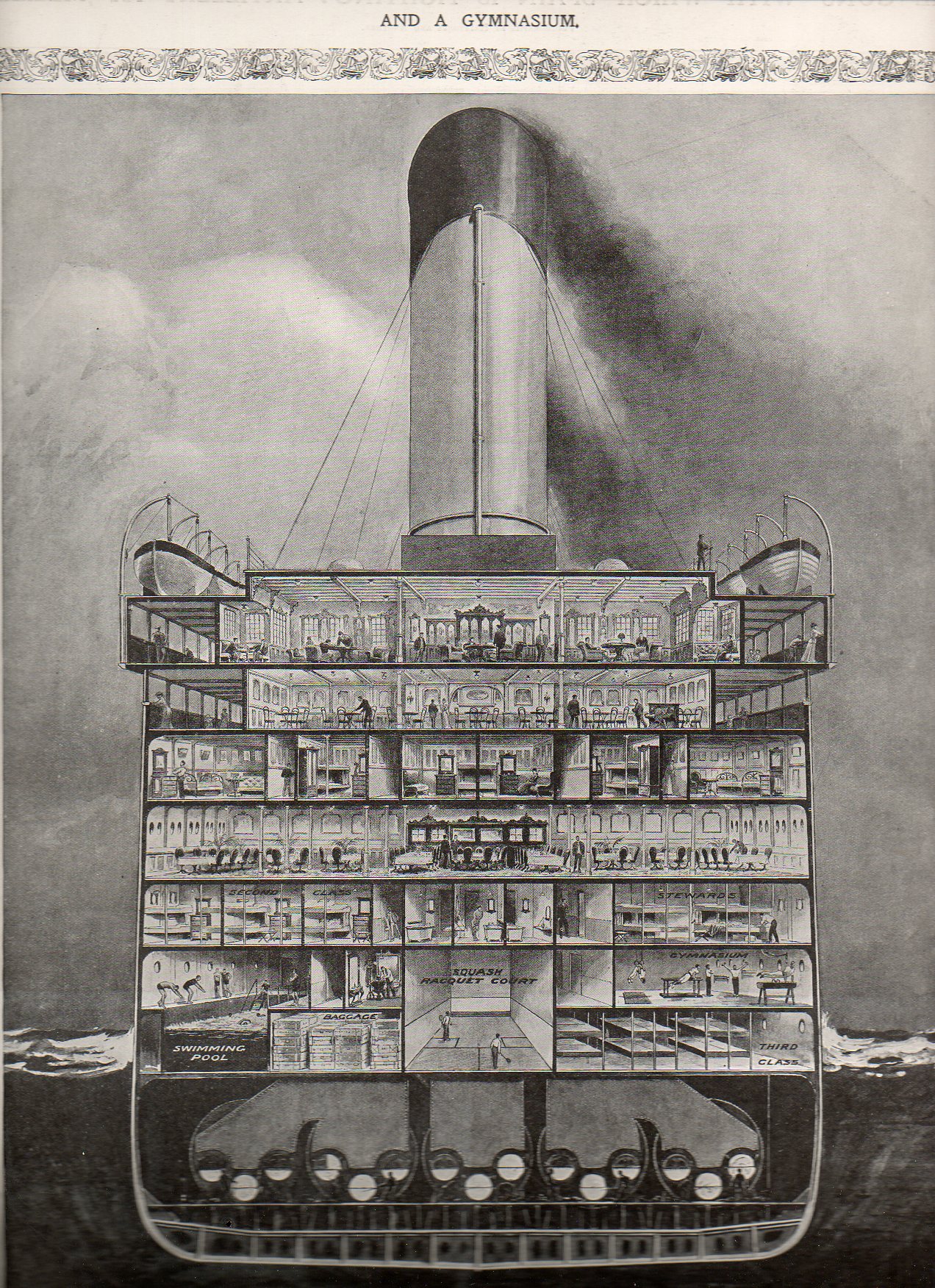
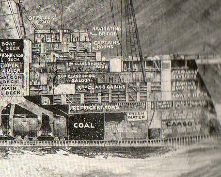
    Resting comfortably in-between this blog’s Cross Sections and Looking-At-Things-Straight-On series is this straight-on cross section of the midship section of the HMS Olympic.

    Cross-sectionship131
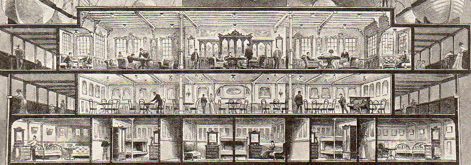
    This cross section appeared in the 14 August 1909 issue of The Illustrated London News, just six months or so after she was laid down. The Olympic was finished in 1911 and sailed through until 1935, a considerably much-longer career than her two sister ships, the Titanic and the Britannic.  The Titanic of course was launched in 1911 and went down on 12 April 1912; the Britannic lasted a little longer, though this ship never really had much of a career, launched just before the beginning of WWI and then used immediately as a hospital ship, striking and being sunk by a mine in 1916.  The three ships were beasts, about 882 feet long and about 53,000 tons displacement. The viewer certainly gets a good idea of the scope of the ship from this image.   [The original image of the Olympic and also of the Mauretania are available for purchase from our blog bookstore.]

    Cross-sectionship132
    Cross-sectionship133

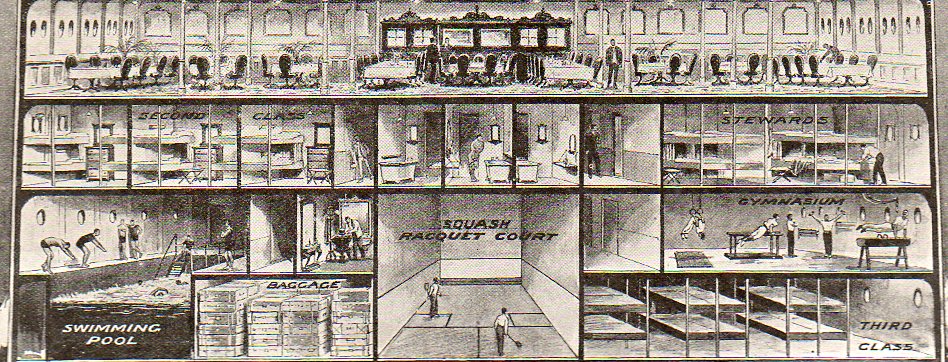
    Third class looks pretty rustic, a no-bones approach to ocean travel, stuffed into the space next to the squash courts and under the gym. 

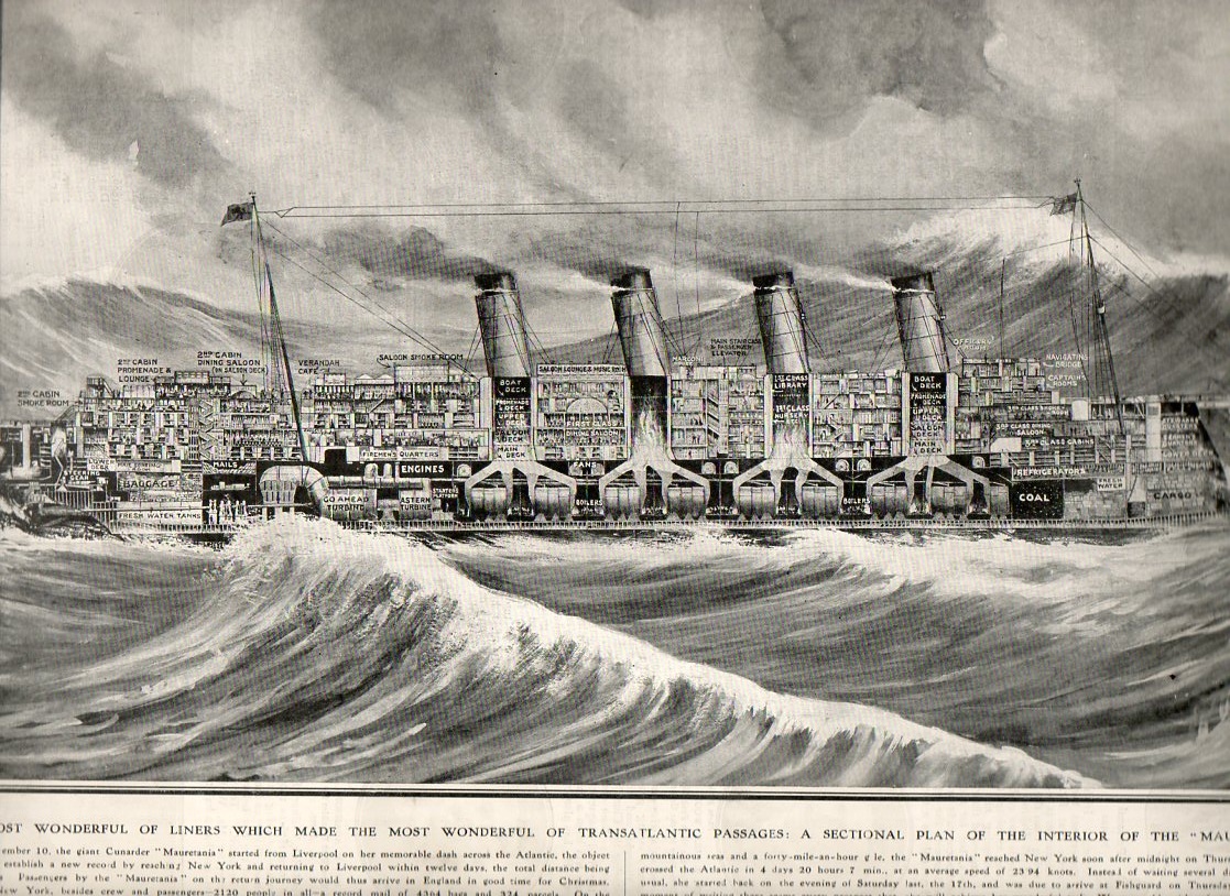
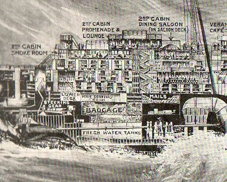
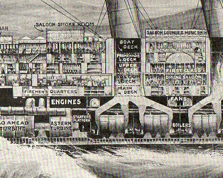
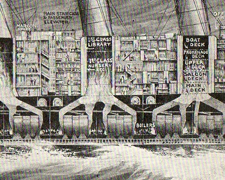
    Next comes the HMS Mauretania, again form The Illustrated London News right at the time of its record-setting speed attempt to cross the Atlantic in November 1907.  The ship was long (almost 800 feet) and about the fastest ocean-going ship in the world,. crossing and re-crossing the Atlantic in 12 days.

    Cross section mauretannia137

    Cross section mauretannia138
      Cross section mauretannia139
    Cross section mauretannia140

    Cross section mauretannia141


  • The First Photo Inside of the Information Revolution–the Transistor, 1949

    JF Ptak Science Books  Post 1370

    Transistor 066

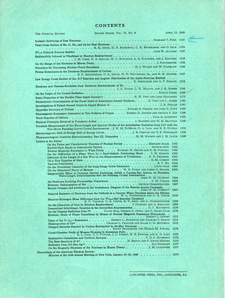
    One of the things I love about working my way through old scientific journals is when I find the issue that I’m looking for and scroll down the list of contributors to find the significant article that I want.  Long list, usually; and then, after making my way through 30 or 40 lines of tight type of the index I find it. [This by the way is one of those experiences that is being replaced by the digital library.]   Even though the paper on pp 1208 through 1226  of the 15 April 1949 issue of The Physical Review looks like any other, it is today seen as revolutionary. The entry for “Physical Principles Involved in Transistor Action” by John Bardeen (two-time Nobel in physics) and Walter Transistor 064 Brattain (Nobel ’72) shows up about halfway down the index, sandwiched in some very good company (Enrico Fermi’s “Origins of Cosmic Radiation” and a number of others), and does not show up bolded, or highlighted, or with an asterisk.  Such is the nature of publication in the academic journal world, everything delivered with equal weight. (The original publication is available for purchase here at our blog blookstore.)

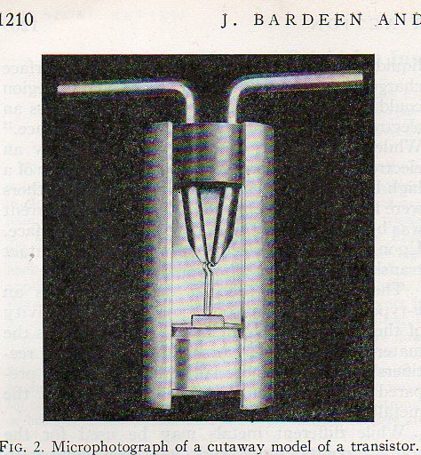
    It makes me wonder though how it would’ve felt to open this journal for the first time back there in mid-April ’49, turning to page 1210 to see the microphotograph of the cutaway of a model of the transistor.  This was the defining technical publication on the transistor1, which was the first massive step towards microminiaturization and the explosive new growth in the computer, allowing far more powerful machines to be designed in far less space, in far less amounts of time, and on and on.  It is one of the first steps in the Information Revolution, moving the computer from massive racks of electronic tubes to more simple, elegant, nimble and by-far faster circuit boards with transistors (and resistors, capacitors, inductors, diodes, etc.) to make an electronic circuit.  This would be the standard for computer construction, only supplemented by Jack Kilby (TI)  and Robert Noyce (Fairchild Camera) in 1958/9 with the integrated circuit, where transistors are made smaller still and produced in groups on circuit boards rather than individually.

    The photo above shows a cutaway of the transistor, and is the first time it was published–the first photo of what was one of teh 20th century’s greatest inventions. 

    Transistor 065

    Notes

    1.  The paper was published simultaneously in the Bell System Technical Journal; Bardeen and Brattain were with the Bell Labs.  The Bell journal also contained another revolutionary paper in the same volume, Claude Shannon’s “Communication Theory of Secrecy Systems”, which is one of the most important early papers on electronics and cryptology.  (We also have a copy of this classic paper for sale at our blog bookstore site.)


  • An X-Ray of Cubism? Jouffret and Visualizing the Fourth Dimension, 1903 and 1906.

    JF Ptak Science Books   Post 1361

    Is this an X-Ray of Cubism?

    Jouffret

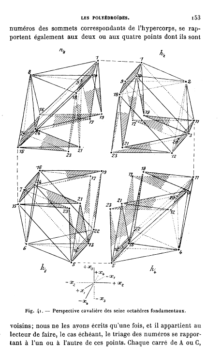
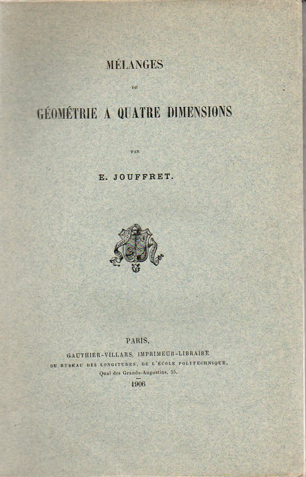
    Emile Jouffret brought an amazing and lovely pair of books to the mathematical dining table, both coming at about the mid-point of a period of perhaps the most sweeping multidisciplinary revolutions in human history.  Published in 19031 and 19062 [and both originals available at our blog bookstore] they both may have had an impact as a visualization tool for the newest movement in art since the creation of Impressionism (1850’s-1870’s): Braque and Picasso’s  Cubism. When you compare the illustrations in the Jouffret books you cannot help but to see a connection to the work of (the morally-lonely) Picasso (and especially in his 1910 portrait of the movement-molding art dealer Ambroise Vollard, below). Georges Braque and the that the two would make in 1906, the first year of the Cubist movement. 

    Jouffret’s 1903 book was hardly the first on the topic, though it may be the first of the major, book-length treatments of the topic, as well as the most  heavily illustrated.  Thinking on the fourth dimension goes back as far as Kant, at least, and the real work begins in the first half of the 19th century.
    The first major3 work arrives with Hermann Grassmann’s “Die Lineale Ausdehnungdlehre” (Theory of Linear Extensions) in 1844 (and the subsequent translations of the work as well as original work by Arthur Cayley); followed by Ludwig Shclafli (1814-1895) “Theorie der vier flachen….” (Theory of Continuous Manifolds, 1852 but not published until 1906), Riemann’s 1854 speech (which was not published until 1867 and which appeared translated by William Kingdom Clifford in Nature in 1873, G.F. Rodwells “On Space of Four Dimensions” (Nature, May 1873),  Dodgson/Carroll‘s  Through the Looking Glass (1872) deep references, Zollner “On Space of Four Dimensions” 

    Jouffret499

    (April 1878 and subsequent publications, and who is referenced in Kandinsky’s [difficult -to-me On the Spiritual in Art of 1912), W.I. Stringham (1847-1909) “Regular Figures in n-Dimensional Space” (American Journal of Mathematics, 1880), and E.A. Hamilton Gordon, “Fourth Dimension”, April 1887, to name some of the major figures.  And then of course comes Edwin Abbott’s Flatland, a Romance of Many Dimensions, by a Square (1884) and Charles Howard Hinton, who published a number of different works beginning in 1880 (“What is the Fourth Dimension?”, 1880 plus Scientific Romances 1884, and The Fourth Dimension, 1904) and lasting through the turn of the century.  There is also H.G. Wells, whose The Time Machine began to appear in parts as early as  1894, though it did appear in the same issue of the  Science Schools Journal as the Hamilton Gordon article, in April 1887, as the “Chronic Argonauts”). Wells’ also approaches the fourth dimension in “The Plattner Story”, in 1896 and The Invisible Man in 1897. Other literary contemporaries of Wells who used the fourth dimension in their work include Oscar Wilde (“The Canterville Ghost”, 1891), George Macdonald (Lilith, 1895), and Joseph Conrad and Ford Maddox Hueffer The Inheritors, (1901)–the most convincing and scientific of all of these literary efforts though lies with Wells. From about this point on–from the time that Jouffret enters the scene in 1903–the fourth dimension has become part of the culture, and a popular culture at that…especially after the Cubists begin their assault on visual representation in about  1906.

    The Jouffret books are beautiful, and very interesting–they would have been better served with a bibliography, which would have been very nice to have–that said, Jouffret does have a fair number of footnotes to earlier work, so it is not as though his work is without attribution.  But it is a very interesting adventure. (Just a note–the fourth dimension and non-Euclidean geometries would get their first bibliography in D.M.Y. Sommerville’s classic  Bibliography of Non-Euclidean Geometry in 1911, which is a must-have for all of those interested in this topic…it is massively packed with all manner of major and minor works as well as obscuriana.  It is not, unfortunately, annotated.)

    1. Jouffret, E.  Traite Elementaire de Geometrie a Quartre Dimensions et Introduction a la Geometrie a n-Dimensions. 

    2.  Jouffret. Melanges de Geometrie a Quatre Dimensions.  Paris, Gauthier-Villars, 1906.  220pp.

    3. Most of the data in this long and winding sentence has been culled from Linda Dalrymple Henderson’s terrific The Fourth Dimension and Non-Euclidean Geometry in Modern Art, Princeton, 1983–most of my references come from the first 45 pages or so of her book, which is the Bible of all modern works on the fourth dimension/math/physics/art.

    Picasso_vollard1910


  • Beautiful Technical Shadowing, 1880

    JF Ptak Science Books    Quick Post

    Techno art wheel488

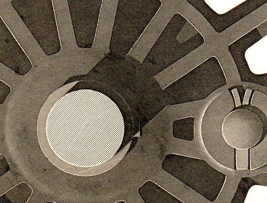
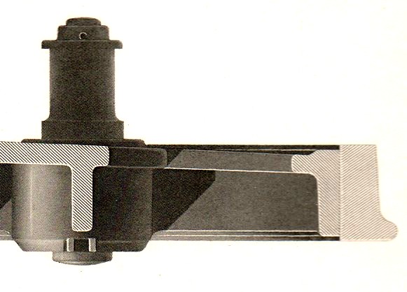
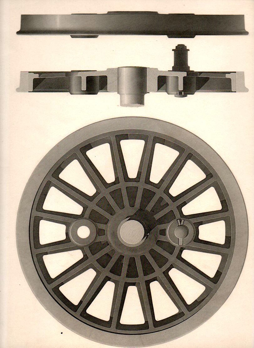
    This superb engraving, “Examples of Finished Shading, Locomotive Wheels” (source unknown) was engraved by J.W. Lowry after the original of C.J. Wallis, and published by Blackie & Son of Edinburgh and London around the year 1880.  The work is detailed yet spare, heavy yet elegrant, beautiful, and of course perfectly shadowed.  Splendid. The details (above and below) could be almost anything, but the first does have a certain pull of the 18th century masters of Fench visionary architects (Boullee, Leduc & co.) to it. The full engraving (which is available at our blog bookstore) is follows the following.

    Techno art wheel489
    And the full engraving: Techno art wheel487


  • Proust Suits and Pressurized Cabins

    JF Ptak Science Books   Post 1341


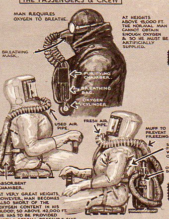
    If I put my literary specs on and do a little free-association,  what I see in these two figures is a Proustian thing, characters in search of time, freezing time, preserving it. Time, and everything else, everything that can be associated with a human experience captured and recaptured, recirculated, resuscitated, replayed, re-envisioned, remembered, recognized, over and over again.  Kind of like a memory hell, in a way, only in Proust’s hands it all sounds and tastes so beautiful. Another peek without those wicked mega-specs and I see two robots from a pulsing Disney film, actions in search of characters–the possibilities are endless, particularly if you develop a little narrative. The real story of what is happening here is complex version of a simpler solution.

    Pressure404

    And the key to it all: hypoxia.

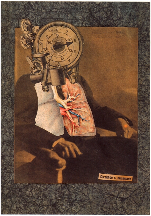
    But I can’t leave this without at least a mention of Raoul Hausmann, whose “Self Portrait of a Dadasoph” is related to this line of collecting consciousnesses:

    hausmann

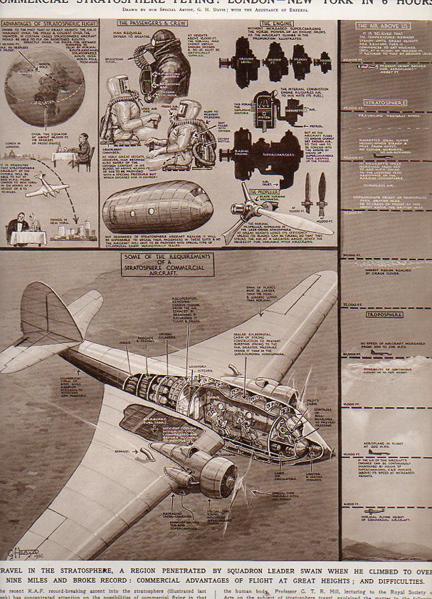
    When this next image was published in the Illustrated London News in October 1936 the practical application of tropospheric flight was just about a reality.  I should really say “popular” more so than “practical”.  It presented two approaches to a looming problem in the progress of aviation–reaching altitudes in excess of 10,000 feet begins to present a host of problems to the passenger of that aircraft.  The solution was to combat the pressures of high altitude flight, one of which was to pressurize each passenger and crew member in their own “space suit”.  The combination of the artist G.H. Davis1 and the technical assistant compared this solution to the problem with a more simple and elegant solution.
    Pressure405
    And that was relatively simple, at least in thought experiments: rather than pressure everyone individually, you could place everyone in a pressurized environment within the aircraft.  And this is the point that the artist/techie make–earlier engineers came up with simple solutions to traveling at high altitudes–they just weren’t simple enough.  And compared with the better design, the initial, simple, designs look a little monstrous.
                                   
    Notes:

    1. I include Mr. Davis as an iconic figure in the history of 20th century technical illustration–he has been featured on this blog many times.


  • WWII Aircraft Cross Sections–the Schematics Work of G.H. Davis

    JF Ptak Science Books  Post 1130

    sI’m sharing some of the collectrion here of the published work of George.H. Davis (1881-1963), the prolific and vastly accomplished artist for The Illustrated London News. His work with that magazine for the forty or so years that I am familiar with is superb, and his great strengths can be found in rendering technical cross sections and infographics.  He had a great sense of design and a very fine hand, and so far as I can tell he displayed an excellent control of his subject, thousands and thousands of times (2,500 times, according to Mr. Davis).

    Here are some fabulous examples of technological cross sections of WWII aircraft by Davis–the drawings are just superb, and you can easily get lost in them, following the geogrpahy of engineering detail from one logical place to the next.

    Blohm u. Voss BV141

    1ebay_sept_24_blohm_voss_141667

    This is the Blohm u. Voss “BV 141″a very unusual-looking aircraft, and it appeared in The Illustrated London News for 23 May 1942, and it gives an excellent view of what the editors called “a lop-sided freak”.  Perhaps the editors of the ILN wanted to educate its readers on the plane since it was supposed to be widely employed on the Russian Front, though it looks like only 38 were ever built (and none survive today). Actually, the plane, designed by Dr. Richard Vogt (1894-1979),  was a high-flying three-seater  surveillance aircraft capable of 220 mph at 17,000 feet, powered by a single 1000 hp Bramo Fafnir 9-cylinder radial engine.  The idea for the design was to give the pilot and co-pilot a very wide field of view–and by this, I’m guessing that the field of view most affected and aided by this would be straight down. The rear gunner also had an enormous field of view. 

    As it turns out Vogt survived the war and spent his Golden Years in the U.S., seven of them (1960-1966) with Boeing to evaluate hydrofoils and vertical liftoff systems:  he had built other odd planes during his career, and carried them with them into near-retirement, making this sort of design his metier.

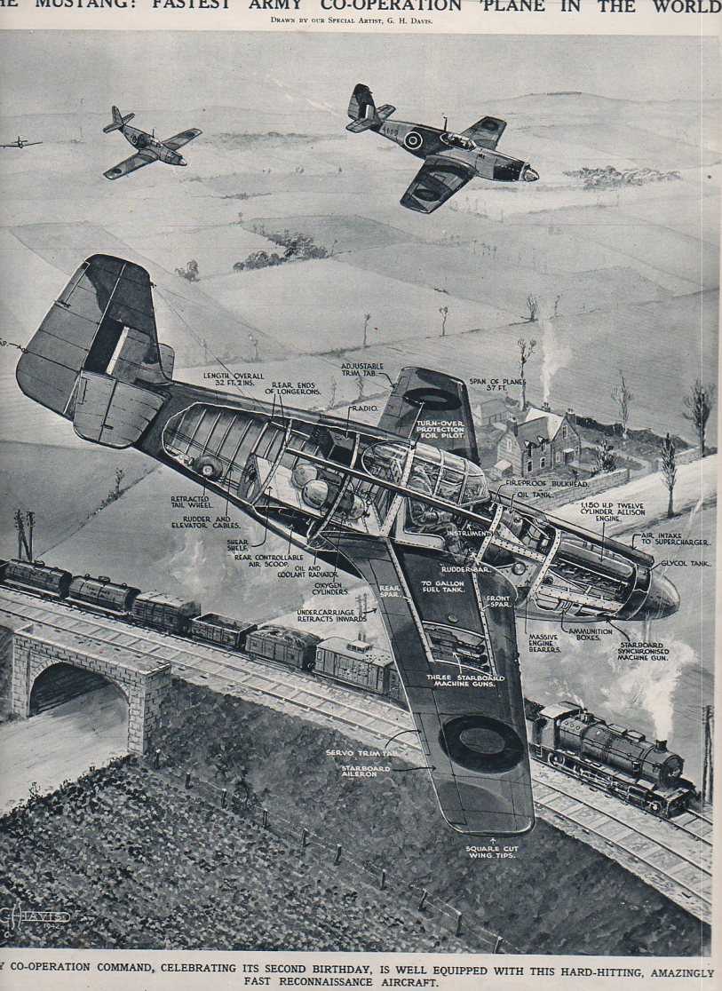
    “The Mustang–Fastest Army Co-operation in the World“, appearing in The Illustrated London News for 12 December 1942. 

    Aircraft x section-mustang849

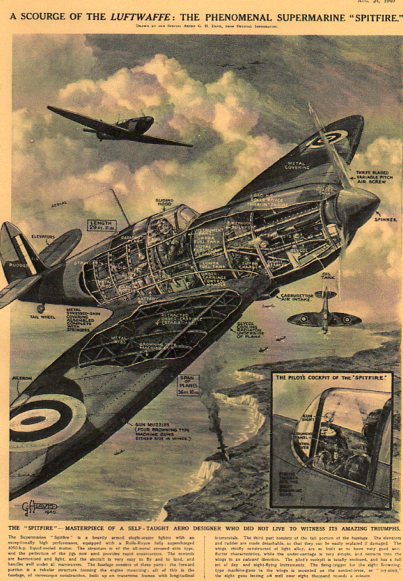
     The Spitfire:

    X-Sect  SPitfire507


  • A Do-It-Yourself Paper Digital Computer, 1959.

    JF Ptak Science Books    Post 1210

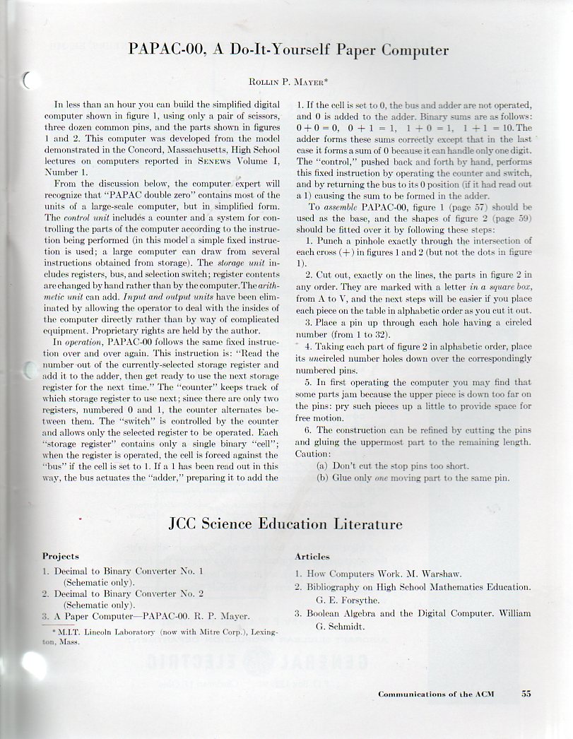
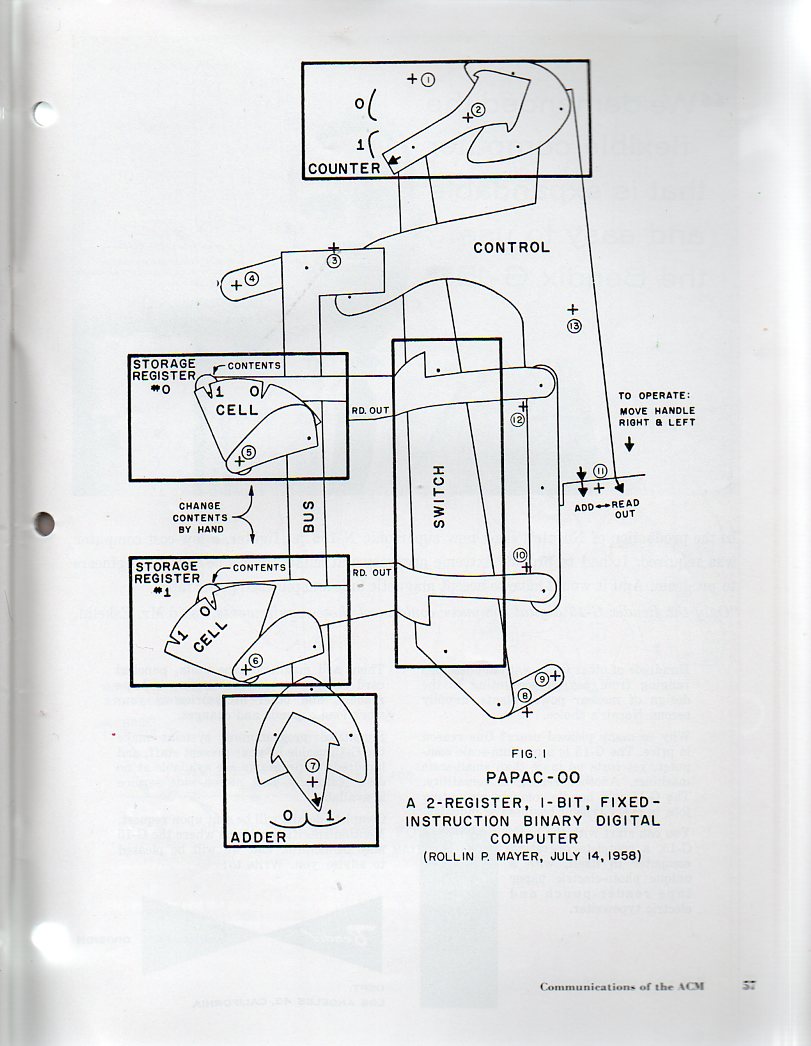
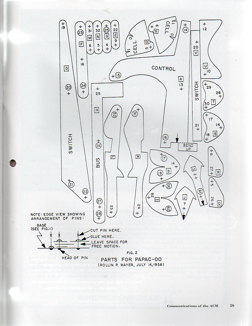
    Computer, paper832 This wonderful cut-away and paste-up template for a digital computer comes to us from the Communications of the Association for Computing Machinery, volume 2, issue 9 for September 1959.  The PAPAC-00 is a “2-register, 1-bit, fixed-instruction binary digital computer” and was submitted to the journal by Rollin P. Mayer (of the MIT Lincoln Lab).  There’s a hunk of me that wants to make this thing really big–cut out the individual pieces and then crash them out to 50″ widths, pasted on found bits of cardboard packing from the neighborhood frame shop, and then piece the thing together as the world’s largest pre-1960 1-bit paper computer.  Or maybe not.  In any event I thought to share this with readers here who might actually print out these templates and try to construct the thing themselves–warning: you’ll need t be able to cut pins in order to make the model work properly. Computer, paper833

    Mayer also wrote an interesting article on including children in the scope of the computer industry…in 1956–something I find to be a very early piece of thinking on Little Humans and Big Computing.  His abstract identifies the three main points of his paper: “(1) That the digital computing field needs, and will continue to need, not only more people who are capable of designing and programming digital computers, but more people who understand the basic limitations and potential uses of digital computers; (2) that the computer industry should take an active interest in providing a basic computer training to the largest number of people, in addition to more extensive training to those who show an interest in designing and programming computers; and (3) that the typical 12-year-old youngster has the interest, skill and basic knowledge necessary to build and understand simple working models of practically anything”. –“A proposal for training youngsters in digital computing techniques” in Proceeding ACM ’56 Proceedings of the 1956 11th Annual Meeting.

    Lastly I should also mention that in this same monthly issue (which ranged all of 52 pages) was an article by Julien Green, “Remarks on ALGOL and Symbol Manipulation”, a three-page paper that comes from the near-dawn of the ALGOL (short for ALGOrithmic Language). (It can be argued that the beginnings of ALGOL were about 1955, but for the sake of simplicity here I’ll note that the first committee appointed to study the matter for the ACM was in September, 1957, and the first group to formalize it met at the ETH Zurich in 1958, producing the language’s first version, known as ALGOL 58.  Julien Green was a member of the 13-person panel that created the ALGOL 60that met in Paris in January 1960.   And so the Green paper did appear within the first few years of institutional study in America, and it was written by one of the six American members of the ALGOL 60 team.)

    Computer, paper834


  • WWII Aircraft Cross Sections–Spitfire, Hurricane, Beaufighter, Lancaster (!) and Stirling.

    JF Ptak Science Books    Post 1165

    Here are some fabulous examples of technological cross sections from the collection here–this part concenrtrating on some of the British WWII aricraft.  The drawings are just superb, and you can easily get lost in them, following the geogrpahy of engineering detail from one logical place to the next. All of these images were published in The Illustrated London News and appeared 1940-1943.

    X-Sect  SPitfire507

    And the detail (sorry for that–the originals are much larger than the scanning bed would allow…)