A Daily History of Holes, Dots, Lines, Science, History, Math, Physics, Art, the Unintentional Absurd, Architecture, Maps, Data Visualization, Blank and Missing Things, and so on. |1.6 million words, 7500 images, 4.9 million hits| Press & appearances in The Times, Le Figaro, Mensa, The Economist, The Guardian, Discovery News, Slate, Le Monde, Sci American Blogs, Le Pont, and many other places… 5000+ total posts since 2008.

Category: Technology, History of

  • Revolutionary Lines (1811)

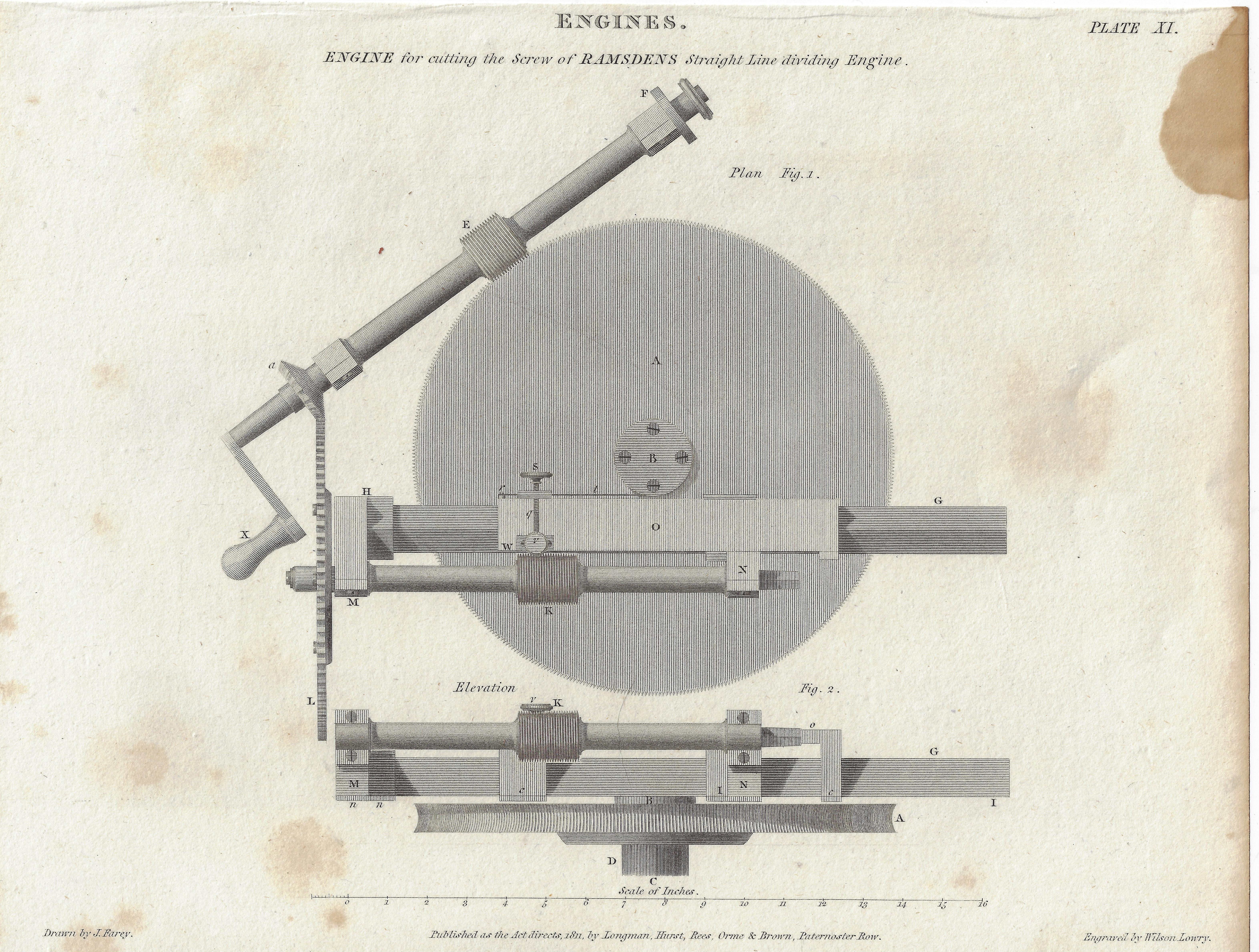
    Here’s a very fine example of a beautiful piece of engineering and a lovely rendition of it. The artwork is an engraving found in Abraham Rees’ monumental Encyclopedic Dictionary…,and was published in London in 1811. It shows in exquisite detail the straight line dividing engine of Jesse Ramsden (1735-1800), which here is being used as “an engine for cutting screws”.  A person could crawl all over this image in varying degrees of microscopic inspection and find  beautiful internal images nestled within the larger drawing in a Ken Burns/fractal-y way. 

    [Click on each image for a better resolution–seems as though this is restricted in a general view by my host]
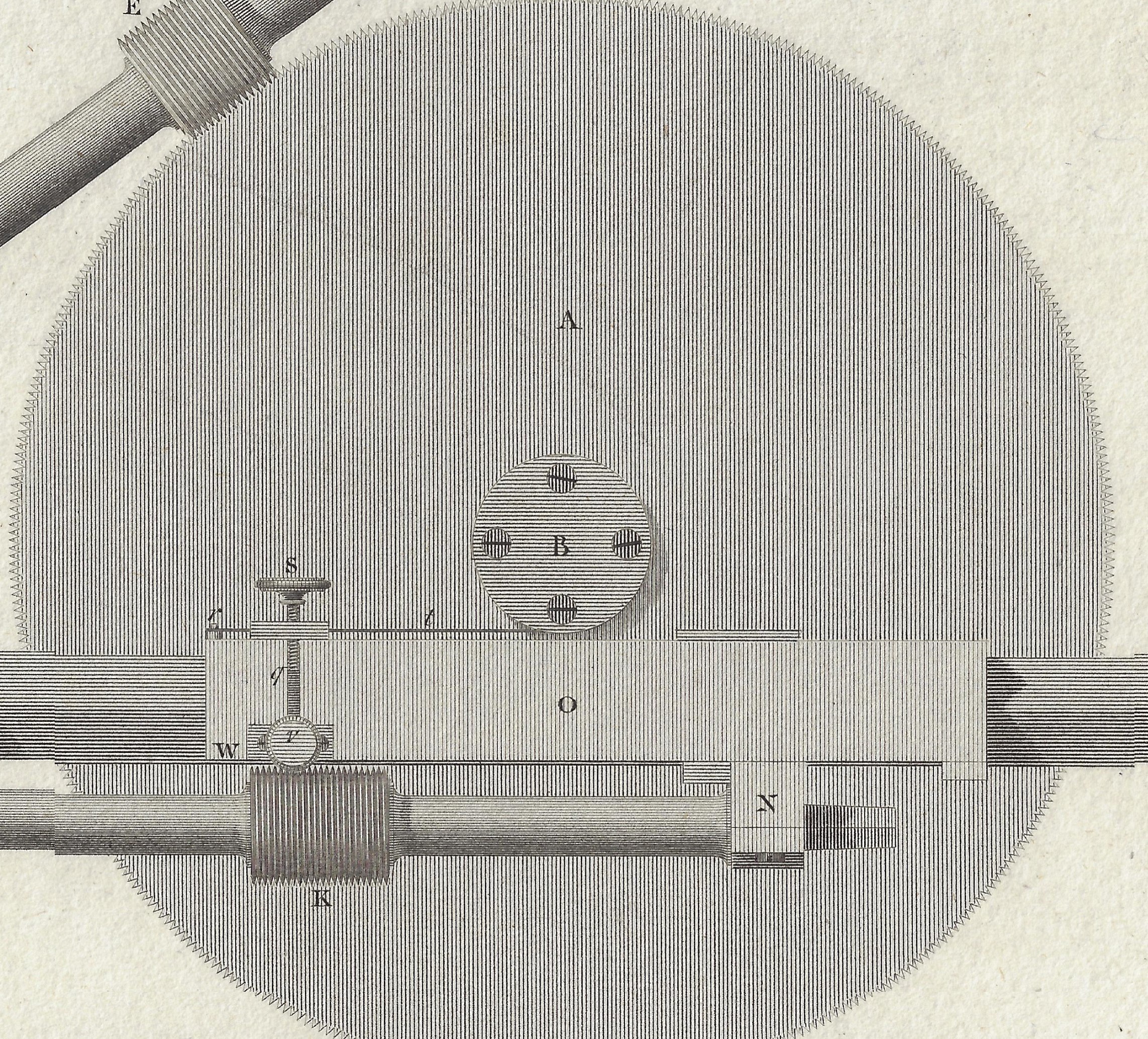
    Ramsden _2_

    This and other similar inventions by  Ramsden’s were key additions to the developing scientific technologies of the Industrial Revolution, integral improvements necessary for integral improvements. (And as we see below in the Wiki quote on this subject, one of the very first things that Ramsden fabricated with his new and accurate lathe was to construct and even more accurate lathe before getting to work–that is an essential and brilliant idea.) Simply put, to make something more precise you need a more precise instrument, and this is exactly what Ramsden made. 

    Ramsden _3_

    And the full engraving:

    Ramsden _1_

    Notes:

    From Wikipedia–“The first truly modern screw-cutting lathe was likely constructed by Jesse Ramsden in 1775. He appears to have been the first person to put a leadscrew into actual use (although, as Leonardo’s drawings show, he was not the first person ever to think of the idea), and he was the first to use diamond-tipped cutting tools.  His device also included a slide rest and change gear mechanism. These form the elements of a modern (non-CNC) lathe and are in use to this day. Ramsden was able to use his first screw-cutting lathe to make even more accurate lathes. With these, he was able to make an exceptionally accurate dividing engine and in turn, some of the finest astronomical, surveying, and navigational instruments of the 18th century.”
    ·Posted by :

    ·in:


  • Not Sci Fi (1929)

    JF Ptak Science Books   Quick Post

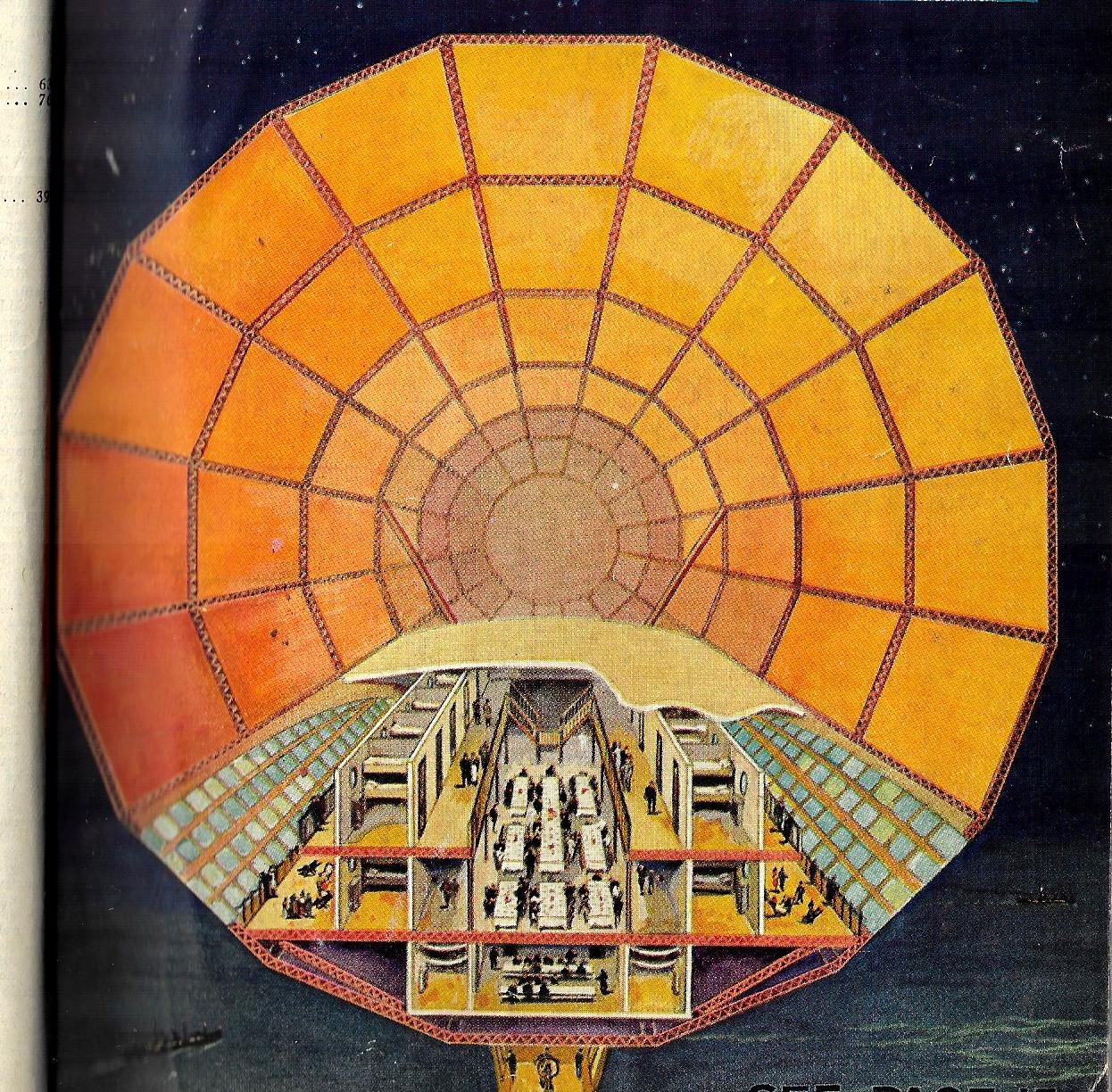
    Pop Mech 1929 cross section airship

    [Cross section for what would be His Majesty’s airship R100 (I think), from Popular Mechanics, January 1929.]

    At first this image looked like the cover of one of Hugo Gernsbach’s science fiction magazines given the number of dining tables and sleeping quarters, but no–it is the front cover of the January 1929 issue of Popular Mechanics showing what I believe would be a cross section of the airship R100. It would be easy to assume that this was an artist’s creative attempt to show  the interior of a rigid airship sometime in the future, given the size and scope of the accommodations for the passengers. But as it turns out, it is a drawing of the interior of what I’m pretty sure would become the British airship R100. The article appeared just months after the first commercial transatlantic rigid airship flight, a 111-hour accomplishment by the Graf Zeppelin (LZ-127). Seven months later, in August, the LZ-127 would make the first around the world flight in 21 days.  The R100’s first flight would occur four months later on 18 December 1929, all 719′ feet of her (with a massive 133′ diameter), with her crew of 37. 

    [I’m not an historian of rigid airships or of flight in general, but it looks to me that the cross section is in accordance with others showing the interior of the R100. Correctly identified or not, the image of the concept is lovely]


  • A Few Circular Ships (Some Submerged and Semi-Sugmerged) 1868-1880

    JF Ptak Science Books     (Expanding an earlier post)

    I’ve noticed a few interesting articles on the circular ship from mid-late 19th century; I don’t really have much to say about them except that I appreciate their structure and, well, beauty, and so I’m just sharing them here. 

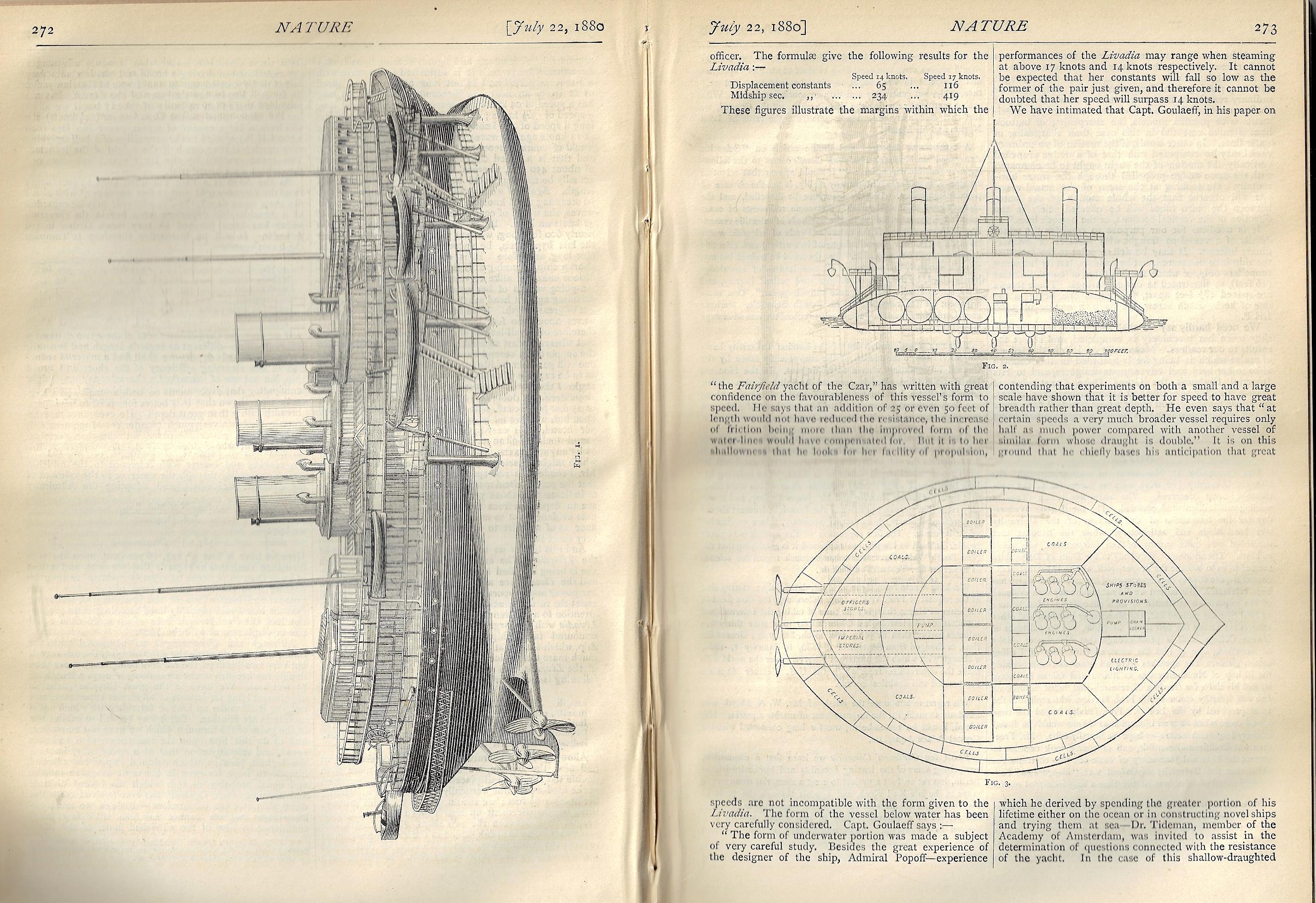
    First is “The Russian Imperial Yacht, ‘Livadia’”, which is an article in Nature, July 22, 1880, appearing on pp 270-274, with several large illustrations, including an elevation and a plan of the ship.  

    Nature 1880 Lividia

    “The Livadia was an imperial yacht of the House of Romanov built in 1879–1880…intended for service on the Black Sea…a radically novel ship conceived by Vice Admiral Andrey Popov, designed by naval architect Erast Gulyaev and built by John Elder & Co. of Govan on Clyde. The Livadia continued Popov’s line of circular shipsalthough this time Popov sacrificed geometrical perfection for seagoing capabilities. She had a beam of 153 ft (47 m) against overall length of only 259 ft (79 m). An extreme example of tumblehome architecture, she sported a conventionally shaped superstructure mounted on a wide, flat-bottomed, turbot-shaped submerged hull or pontoon. The Livadia turned out a surprisingly maneuverable and stable ship with a respectable maximum speed of 15.7 knots and her efficiency was comparable to conventional ships. Her performance at sea trials surprised most naval architects and was attributed to the favorable placement of the propellers.”–Wikipedia

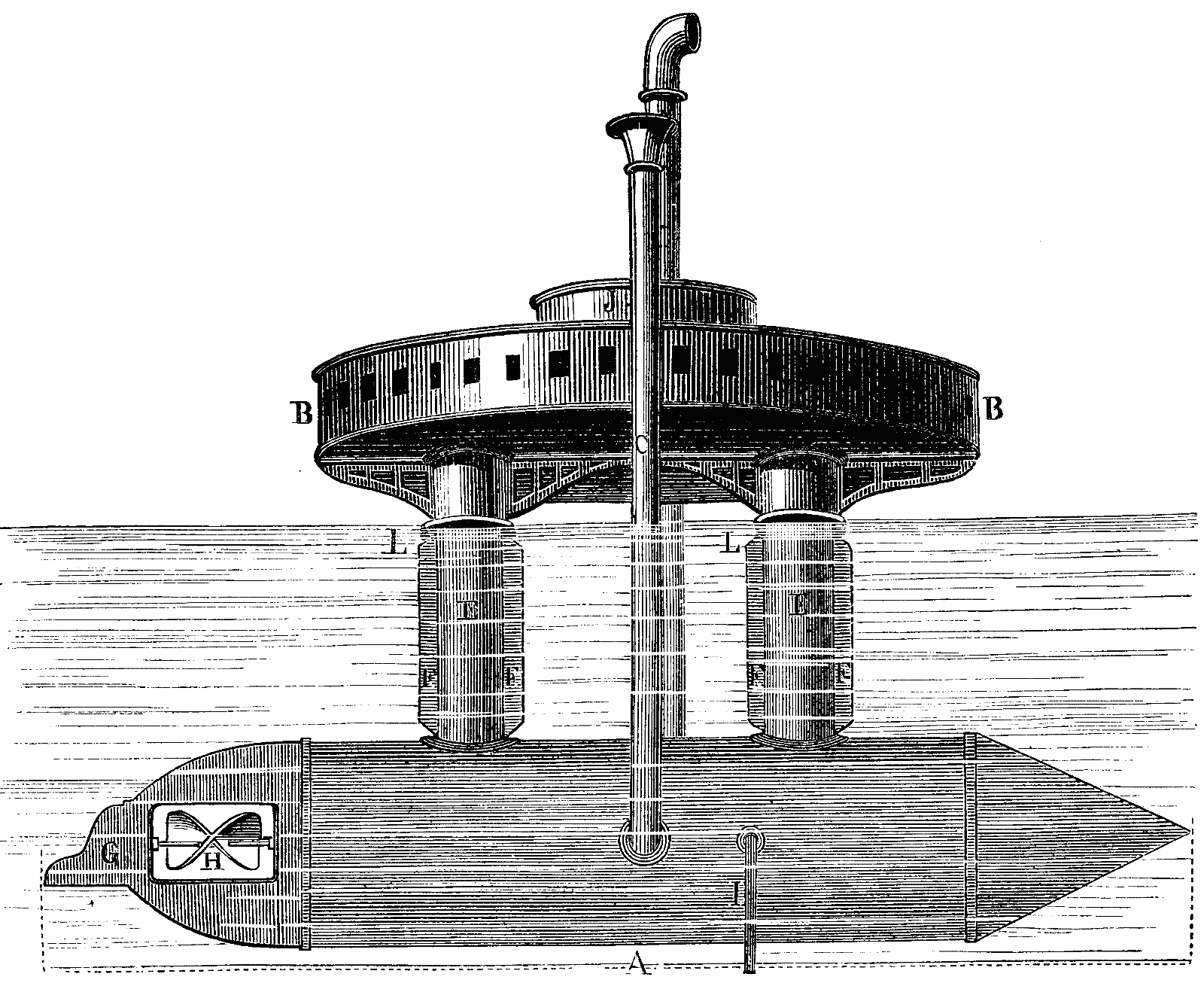
    Next is this fantastic set of drawings for a proposed circular semi-submerged ship, the work of Donato Topmmasi of Paris, and which appeared February 24, 1877, in the Scientific American, page 115.

    Submerged ships tommasi a


    ·Posted by :

    ·in:


  • Heavy (Underground) Metal, 1910

    JF Ptak Science Books  Quick Post

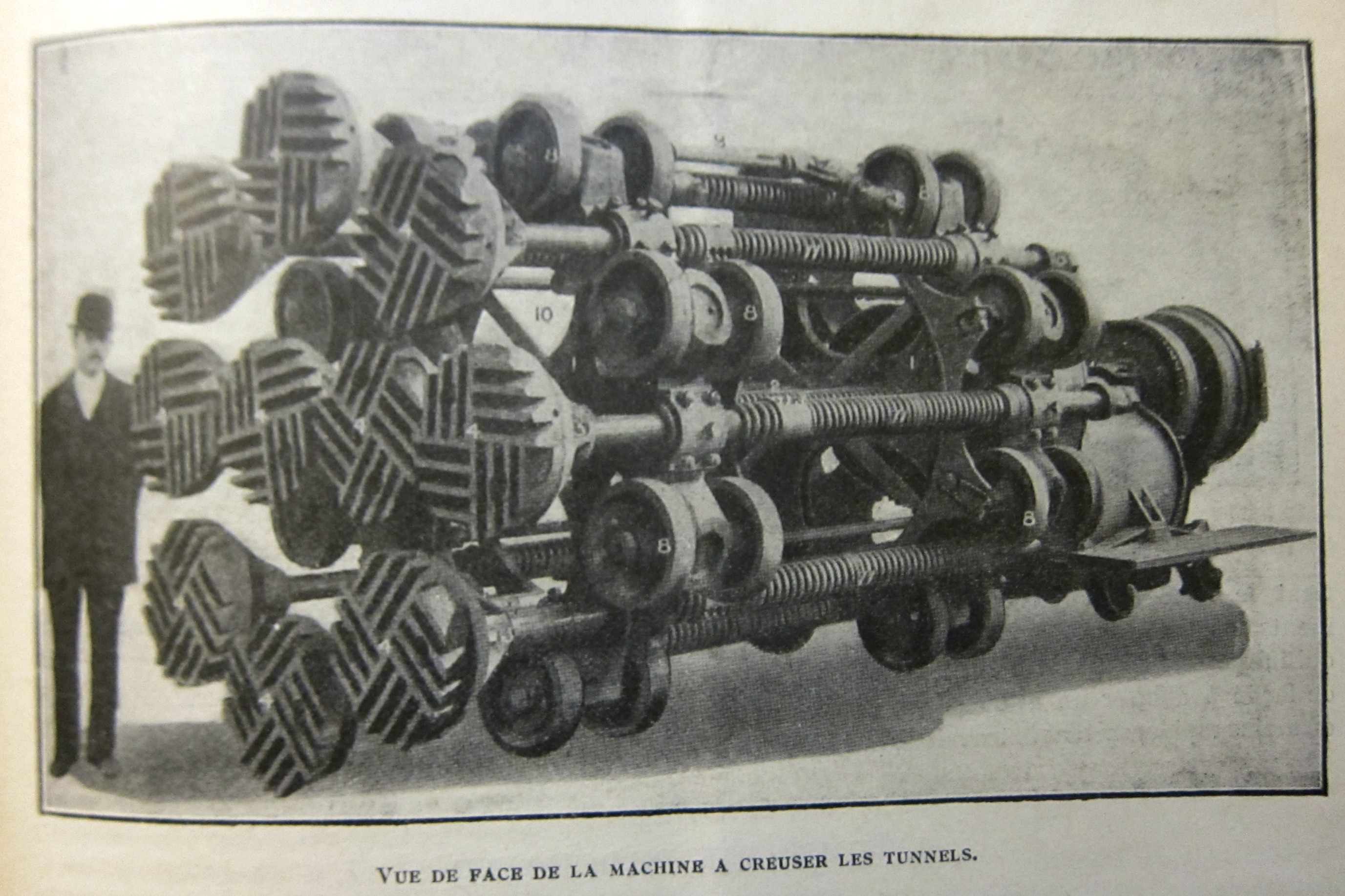
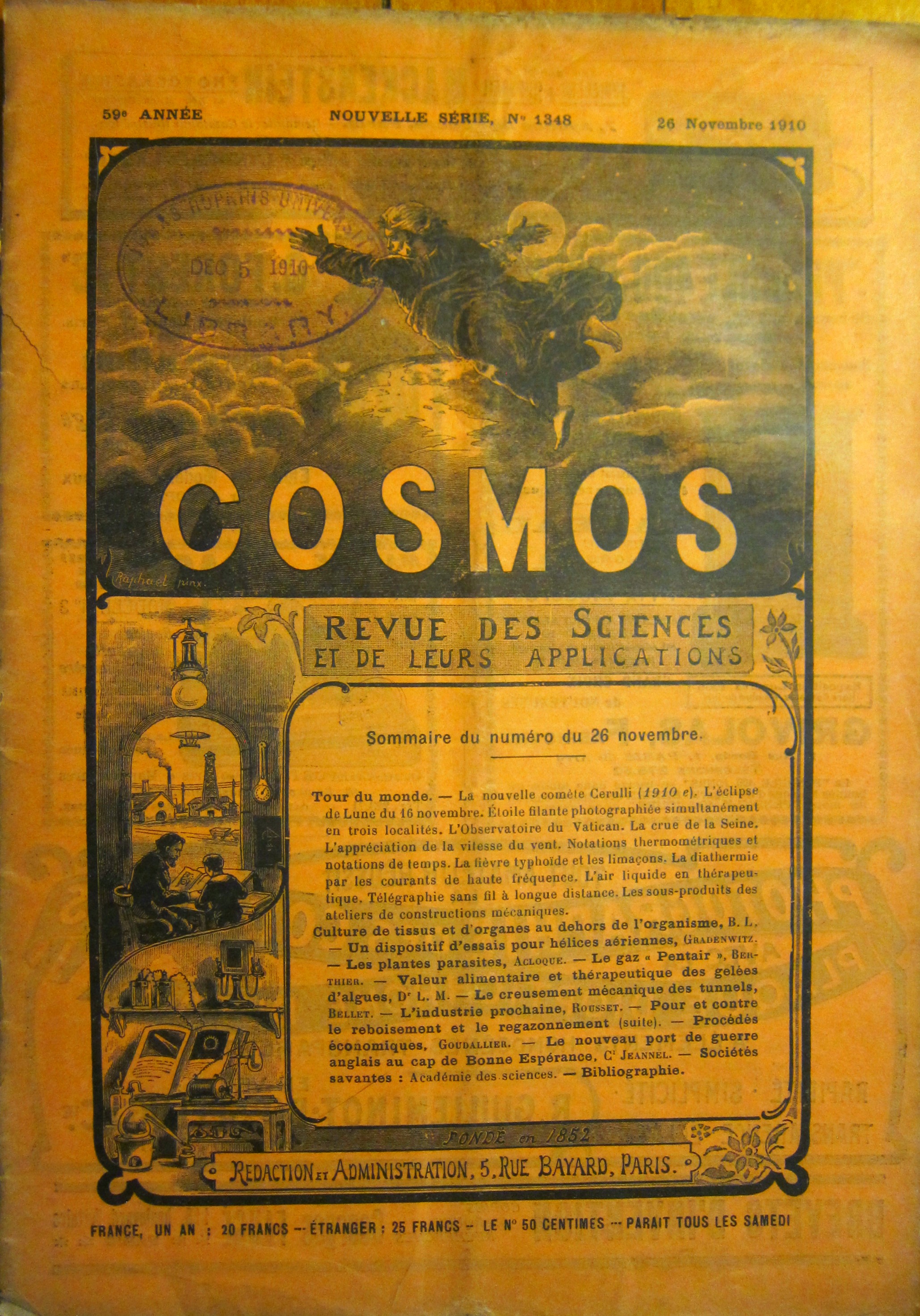
    This is a beast, and the beast was a tunnel digger. This image is from the article “Le Creusement Mechanique des Tunnels” and is captioned “Vue de face de la machine creuser les tunnels”, with “creuser” meaning to dig, and the entire thing meaning, simply, “front of the tunnel digger”, though it sounds much better in French. It appears in Cosmos, Revue des Science et de Leurs Applications, which was published in the weekly issue for 26 November 1910.  This is the only science journal/magazine with a cover illustration featuring the Creator of the Universe.  

    What a wonderful thing this machine was, though right after I think of how many backs of laborers it saved, I am moved immediately to what an engineer would do if the machine got stuck.

    Cosmos November 1910 _2_

    Cosmos November 1910

    ·Posted by :

    ·in:


  • A Flamingo-Legged Boat of 1876

    JF Ptak Science Books   Quick Post

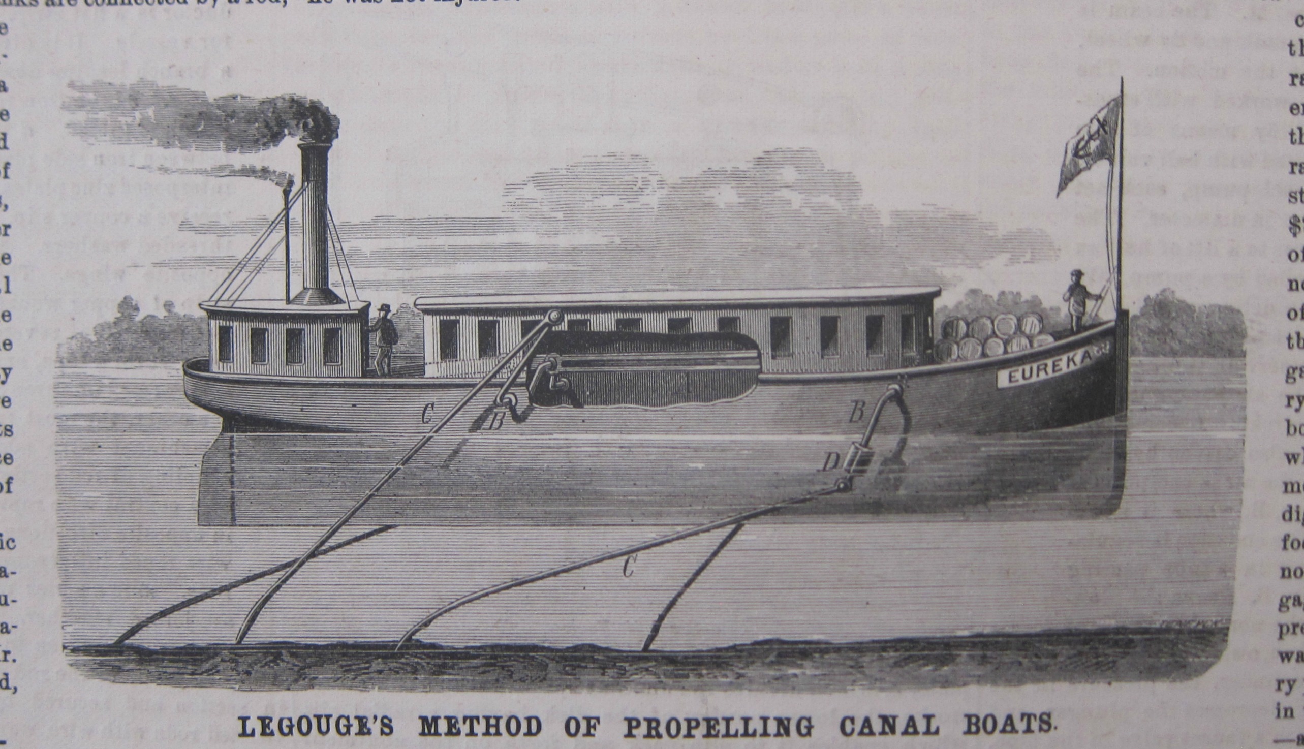
    Sure, I’m poking a little fun here at this propulsion system, but the “legs” do remind me of a flamingo’s. The article, “Improved Method of Propelling Canal Boats” (appearing in Scientific American for December 9, 1876) details their function, and I must say, the thinking and engineering were of high quality in spite of the overall efficacy of the plan.  The inventor, Louis F.A. Legogue, developed the engine and an articulated series of push bars that were connected to a steam-powered crank and wheel which in its complete revolution pushes the bar obliquely down (resulting in it pushing the boat forward) and on the return revolution the bar is pulled up again ready to by pushed down. And so the canal boat would makes its way in the water. That would have taken this job away from humans, whose job it was to do pretty much the same thing, only without steam. (They also remind me of one of those cartoons in Punch magazine in the 1870’s of long-legged gentlemen pushing their way into a headwind without mussing one moustache hair.)  

    SciAm 1876 creeping canal boat


    ·Posted by :

    ·in:


  • The Progression of Construction of a Hawker “Hart” R.A.F. Day Bomber (1934)

    JF Ptak Science Books  Quick Post

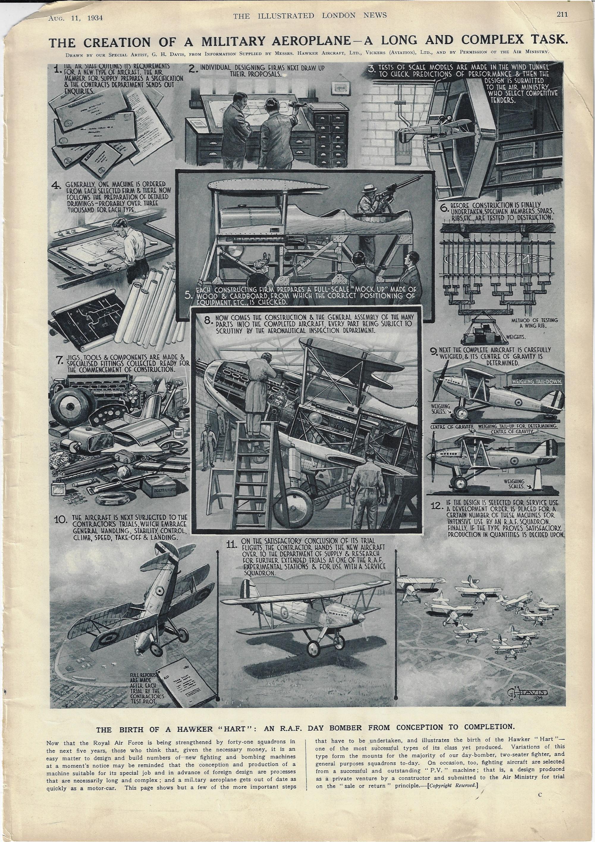
    I enjoy stages-of-construction series of illustrations, showing how cars are made, or boxes, or trenches, and so on.  Sometimes the object being constructed is relatively simple enough and the components few enough that the thing could actually be built from the series of pictures–most of the time, this is not the case, though they do give a good idea of the procedure of construction and the background to it. “The Creation of a Military Aeroplane–a Long and Complex Task” by the prolific and highly detailed G.H. Davis for the Illustrated London News (August 11, 1934) is a good one-page example of this process:

    Dataviz Hawker HArt aircraft 1934


  • Ghosts of the Past and the Future (1932)

    JF Ptak Science Books  Quick Post

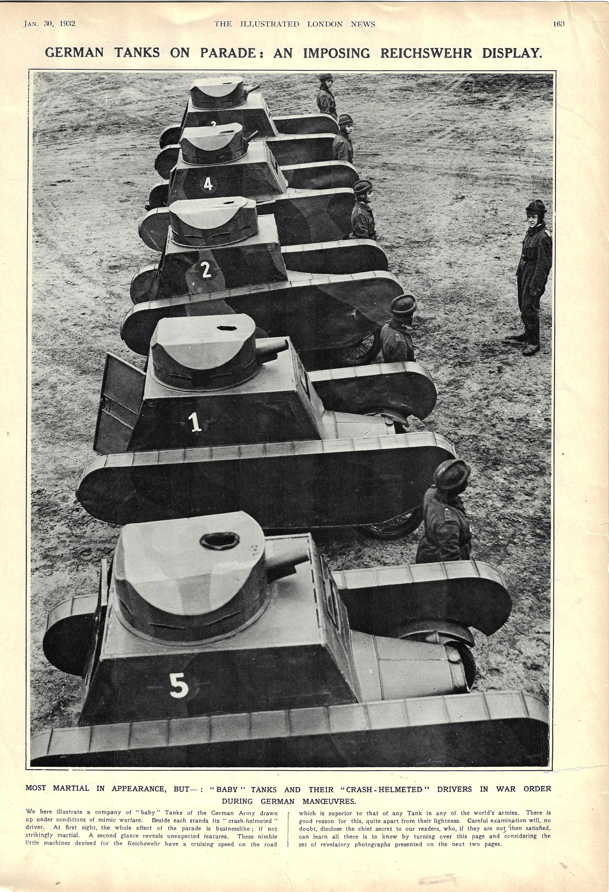
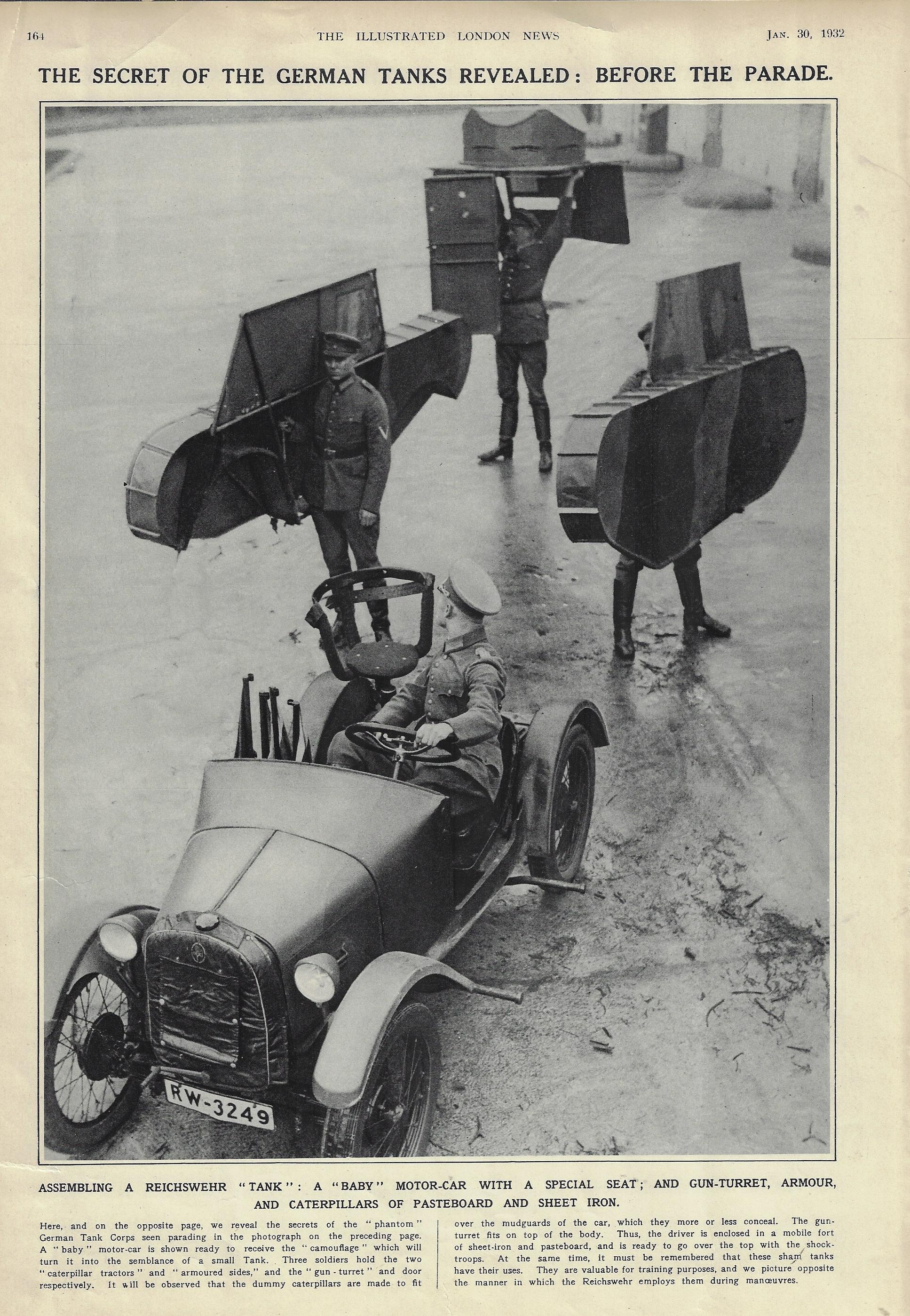
    The folks over at the Illustrated London News were having a bit of a sotto voce chuckle at the expense of what was left of the German military’s tank corps. No doubt its readers were momentarily surprised and probably shocked to see a line of German Reichswehr (the military organization from 1919 to 1935, after which it was the Wehrmacht) tanks–which were prohibited to Germany via Article 171 in the Treaty of Versailles–at least until they sharp-eyed what the “tanks” were or read on in the article. The vehicles were actually just cars fashioned to look like tanks for war games, and that was all. There really wasn’t much to laugh about, though, because the clock was definitely running out on the new normal of world affairs.

    Tanks german 1932 _1_

    This picture story appeared in January 1932, 13 years after the Treaty of Versailles and only a year or so before it began to unravel in earnest. Germany–reeling still from the Depression and from the economic hardships and concession placed on it by the treaty, suffering large unemployment and with a disastrous economy–by June of that year had decided to ignore the military restrictions of Versailles and sought to rearm.  By July it withdrew from the nearly half-trillion-dollar (in 2017 American dollars) concessions agreement, and started to accumulate funds for a vast new military restructuring program. Hitler lost the presidential election later in ’32 but pulled in 38% of the vote and truly began to consolidate power, and a year later he was chancellor with huge Nazi gains in the Reichstag (which would be on fire in another month).  In six years came the Anschluss and Czechoslovakia, and in the next year, Poland, and WWII.  Seven and a half years from cutout tanks to the Blitzkrieg and Rommel and Guderian. This could well have been the last laugh at the German military. 

    Tanks german 1932 _2_

    ·Posted by :

    ·in:

    —

  • A History of Blank, Missing, and Empty Things, Part 42: the Dirt-Filled Tunnel (1895)

    JF Ptak Science Books   Quick Post

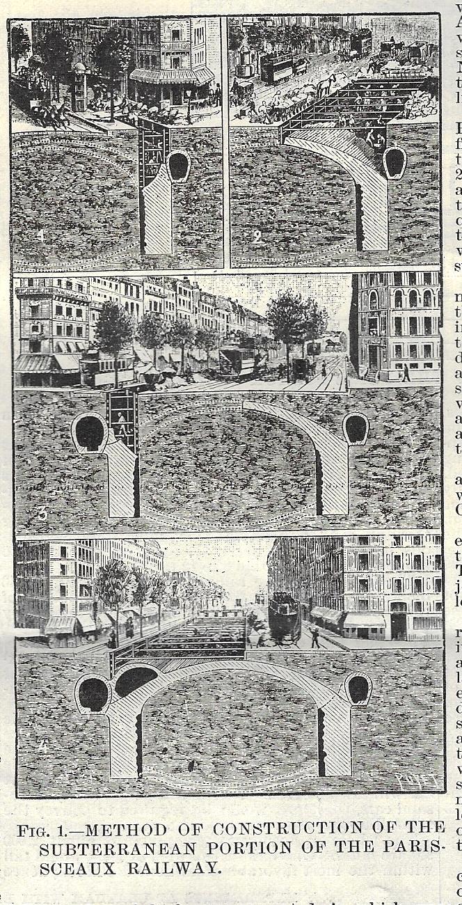
    Sometimes things are very obvious–so obvious that they hide in themselves, in plain sight. That was sort of what happened here, with these cutaways of subway tunnel construction in France in 1895. When I’m reading something to figure out what it is in order to place it in the Books for Sale section of this blog, trying to determine what it was beyond the thing that looked so obvious, it only takes one short sentence or fragment to wrap the whole thing up, and to validate the achingly obvious thing to be exactly what it seemed to be. Such is the case here, with the construction of the extension of the Paris-Sceaux railway (as reported in the Scientific American Supplement for May 11, 1895). Now it seems that in the four-section cutaway showing the progress of work that the workers first dig a deep trench and then construct a masonry “archbutment”, taking most of the sidewalk but not the street during the construction process. Once this is finished, part of the street is closed and the construction of the tunnel ceiling is built for the arch. That done, the work gets flipped to the other side of the street and repeated, though from this end the arch of the tunnel is joined, and the whole of it covered by earth and roadway, again.

    Sci Am SUpp 1895 tunnel detail

    [This small 2×4″ image is a detail from the front page of Scientific American Supplement, May 11, 1895.]

    Then the magic sentence appears:

    • “(F)inally a tunnel filled with earth was obtained”.

    How lovely! And of course, how obvious it is, in spite of looking at the procedure and thinking it somehow ‘backwards”.  Then:

    • “It was only necessary to clear this and establish a floor, and then the thing was finished.”

    There was still track and stations and electricity and ventilation and all of the rest to be installed, but once there was a place to put those things that was not simply dirt, it would be much easier.

    As they say here in the South, “It is what it is”. 


  • Cross Section and Cockpit of a Hawker Hurricane, 1939 and 1942

    JF Ptak Science Books  Quick Post 

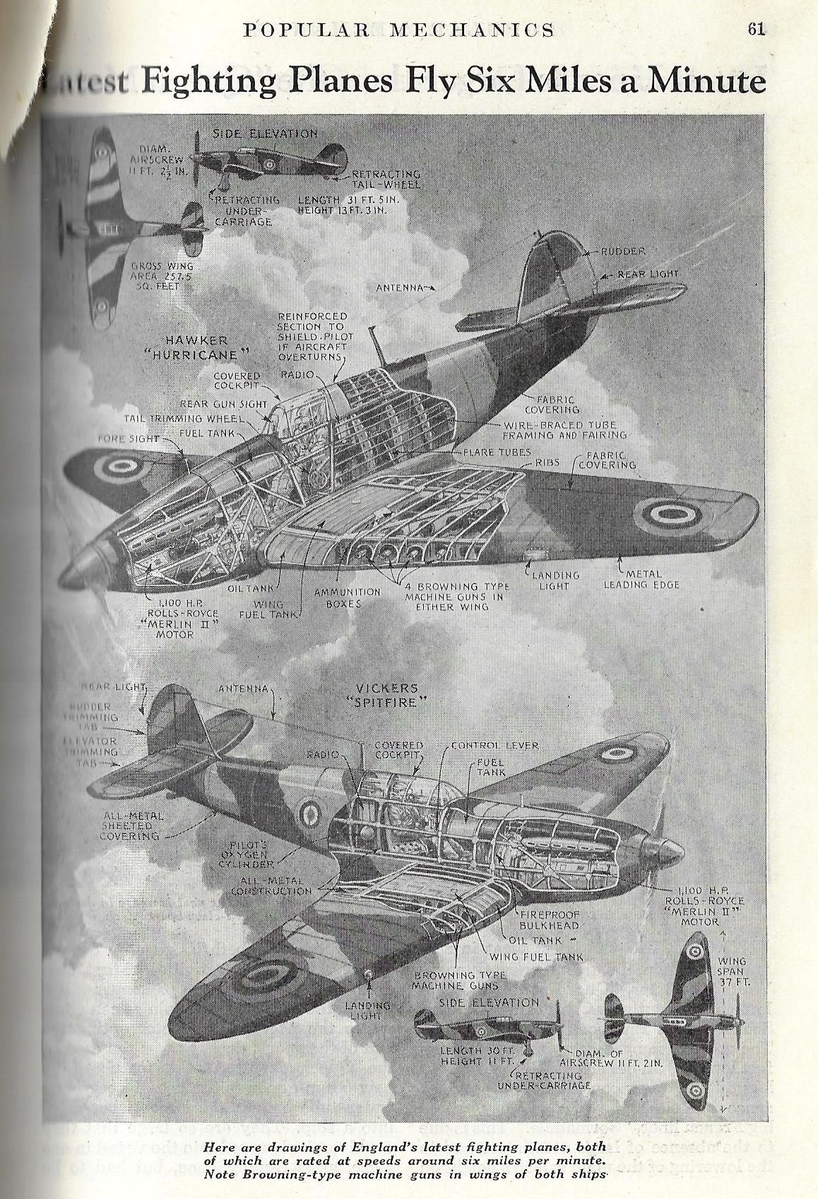
    I would say that there are perhaps 100 good, solid (mostly technical) cross sections on this blog, and to that number I’d like to add two more. the first features the Hawker Hurricane and the beautiful and winning Vickers Spitfire–two of the most important aircraft of the war and backbone of the RAF, and it appears as a short article right before the start of the European part of WWII in Popular Mechanics for January 1939.

    Cross section 1939 Spitfire Hurricane

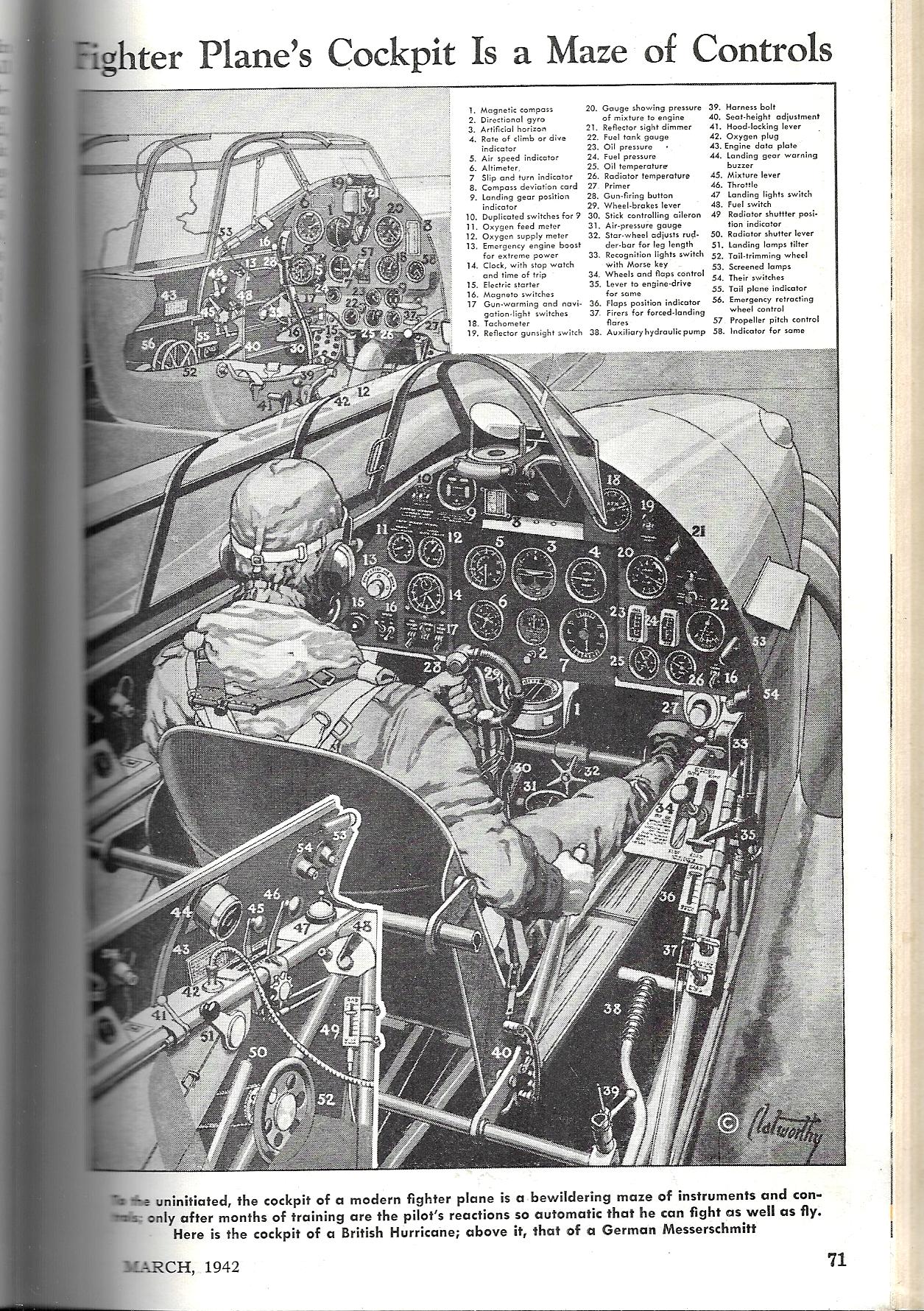
    This second image–barely a cross-section as things go but it does serve our purpose–comes via the cross-section-dependable Popular Mechanics for April 1942, and shows the cockpit controls for a British Hurricane as well as a smaller image for a German Messerschmidt. (Click and click again to greatly enlarge this image for the small print.)


    Cross section Pop Mech 1942 Hurricane aircraft


  • An Unusual Bird’s-Eye View of NYC from a Rare Source

    JF Ptak Science Books  Post 2728

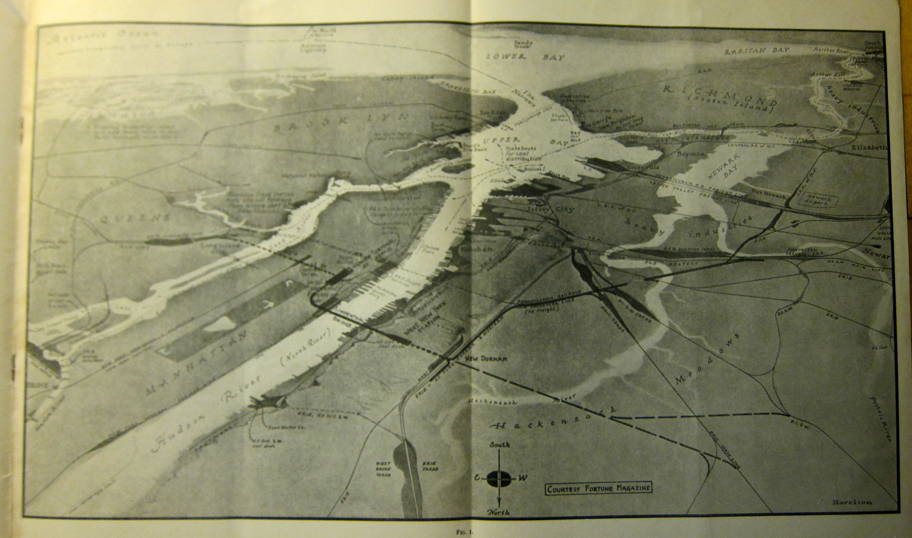
    This bird’s-eye view of the NYC/East Jersey area was found in a rare pamphlet produced by the old North River Bridge Company in 1937. The image–which is widely expandable and found in a pamphlet for a project entitled The Lindenthal Bridge and Terminals, Condensed Statement1—shows the city from a considerable height with a long and oblique view, hovering north of Hoboken on the Jersey side with a view extending to all of Staten Island, which covers a distance of about 18 miles. Heading east (left) in this southerly view we see most of Manhattan, then about all of Brooklyn, highlighting at Coney Island. It is a curious and delightful view. 


    Lindenthal birds eye _4_

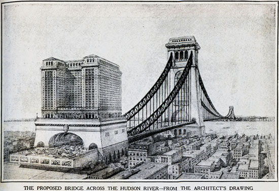
    The “Lindenthal” in the title here is the successful engineer/aesthetician Gustav Lindenthal (of Brno, 1850-1935), who today is most remembered for his wonderful Hell’s Gate bridge (“longest and heaviest steel bridge in the world” according to Wiki), the structure as interesting as its name.  

    An earlier (1895) plan by Lindenthal would have created a perfectly massive structure–as the blog Untapped Cities points out, the 6,000 foot long bridge would have been twice as long as the GW Bridge and its towers would have been the tallest structures in the world at 825′. The bridge would have spanned the Hudson at about Hoboken across to 57th Street, and no doubt would have been monumental if not un-beautiful:

    Lindenthalsbridgesm[1895 bridge image source: http://untappedcities.com/2013/07/25/nyc-that-never-was-hudson-river-bridge-dwarf-woolworth-building/]

    Notes: