A Daily History of Holes, Dots, Lines, Science, History, Math, Physics, Art, the Unintentional Absurd, Architecture, Maps, Data Visualization, Blank and Missing Things, and so on. |1.6 million words, 7500 images, 4.9 million hits| Press & appearances in The Times, Le Figaro, Mensa, The Economist, The Guardian, Discovery News, Slate, Le Monde, Sci American Blogs, Le Pont, and many other places… 5000+ total posts since 2008.

Category: Technology, History of

  • One Word, Three Un-hyphenated (?!) F’s in a Row!

    JF Ptak Science Books   Post 2746

      Luftfff

    I just came upon this fine word, which for a moment challenged my probably under-corrected vision, and saw that it contained three consecutive f consonants! On a Saturday, cranky with a fever and stiff(f) neck, this was a superb BLAST! Or “blast”. Or “b”. Anyway the word is Luftschifffahrft and it occurs in the title of a pamphlet by Wenzel Kotzauer, Die Luftschifffahrt und ihre Zukunft, printed in Vienna in 1895.

    The forty-page pamphlet is about the future of air flight and as fixed-winged aircraft rather than airships, noting in particular the 1894 Hiram Maxim “aeroplane1”. The Maxim machine was prodigious, and was mainly built for testing purposes—it weighed 3 to 4 tons, carried two steam engines that generated 180hp (!) and had pushing props that were 17.5′ in diameter, making the thing a beast-and-a-half. It was fixed to a very wide two-track system to keep it from lifting off the ground when the engines were running—or to keep it from careening around out of control. In any event, Maxim’s dream machine didn’t make it very far and was dismantled after a few years. (He also attempted an unsuccessful return to heavier-than-air flight in 1910.)

    But back to the three Fs. “Luftschifffahrt”, which translates basically to “airplane” or perhaps “aeroplane”, and thus the title is about Airplane/ship/aeroplane Travel in the Future. Or thereabouts. It is a technical work, with much on the actual “aeroplane”, which in its first use were the wings, and here there is much discussion on their size and shape.

    What most interests me though are the repetitive consonants. They just don’t seem to happen in English, naturally, without being hyphenated. (Using the word “un-hyphenated” again I just want to point out its terrific irony!) The word appears with fewer letters as “Schifffahrt”, which is simply “shipping”.

    The most obvious hyphenated candidate for me is “cross-section”, which I use often in this blog, though I can’t kill the hyphen and pulling the two words together as it makes it look like overstuffed snake-sausage: crosssection. As smaller snake is the person who sees a seer is not a seeer, and Scrabble-challenged words like “zzz” and “brrretc” definitely do not count, noooo sir.

    Anyway: fff.

    Notes:

    1.  In general at this time “aeroplane” referred to the wings/airfoils of a plane, not so much as an aircraft itself.  Mostly, it seems. The Oxford English Dictionary says that the first use of the word in this sense occurs in 1866, with a useful explanation of it found two years later:

    All of the following come from the Oxford English Dictionary:

    “Aeroplane”

    1868   3rd Ann. Rep. Aëronaut. Soc. 36   He had turned his attention to the wing and to the sustainer, or what he might call the aëroplane.

    1894   O. Chanute Progress in Flying Machines 237   This main aeroplane..is trussed and stiffened in every direction by wire stays.

    1905   G. Bacon Balloons 111   What are called ‘aeroplanes’—large flat surfaces, light but rigid inclined at a suitable angle to the horizon.

    Aeroplane=aircraft/airplane (as a noun) comes at about the same time:

    1868   Eng. Mechanic 24 Apr. 91/2   We have yet to see the ‘aëroplane’ with buoyancy sufficient to sustain 150 lb., or with apparatus sufficiently light and portable to make headway on an ‘air plane’… Supposing an aëroplane to have raised itself, if it reared out of equilibium it and the occupant would come to grief.

    1873   D. S. Brown in 8th Ann. Rep. Aëronaut. Soc. 17   I think this [sc. impetus] will be more requisite with respect to the aëroplane than any other vehicle.

    1873   Ann. Rep. Aëronaut. Soc. 20   Mr. Bennett introduced an Aëroplane invented by a Frenchman, to be worked by a screw by motive power derived from elastic springs.

    Finally, “airplane” as a noun comes into existence, or nearly so, in the early part of this past century:

    1906   Sci. Amer. 29 Dec. 487/1   Air-plane is a much better word than aeroplane. It is as good etymologically, and much better when it is spoken.

    1907   Westm. Gaz. 19 July 4/2   It is this ease of going against the current, with no motive force in evidence, that is..the despair of the aeronauts with their air-planes.

    1917   N.A.C.A. (U.S.) Rep. Nomencl. Aeronaut. 31   Airplane..This term is commonly used in a more restricted sense to refer to airplanes fitted with landing gear suited to operation from the land. If the landing gear is suited to operation from the water, the term ‘Seaplane’ is used.


  • A History of Big: Massive Aircraft, 1936

    JF Ptak Science Books   Quick Post

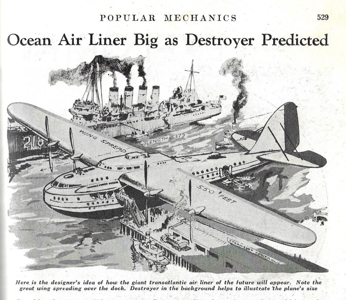
    In the history of aircraft, there’s big, really big, and then Hughes H-4 (“Spruce Goose”) big.  Then there’s the ocean-going aircraft below, found on p. 529 in the 1936 volume of Popular Mechanics. The nameless aircraft would be more than 375′ long and have a wingspan of 550′.  By comparison, an aircraft called the “Stratolaunch” now under construction and designed by Burt Rutan, would have a wingspan of 385′. The “Spruce Goose” was 319′ wide and 216′ long; the 747-8 was 249’wide and 242′ long; and the Airbus A 380-800 stands 262′ wide and 236′ long. In short, of planes having flown, this fabulous thing with the 550′ wings would be twice their size.  

    That said, this giant aircraft was limited not by imagination but by flight of technological fancy. It was supposed to require a crew of 100, fly at only 12k feet at 300mph, and make it across the Atlantic in 11 hours. So, the size was certainly awesome by today’s standards; the tech business end of it, not so much. In any event, the image is quite striking:

    Pop MEch 1936 massive plane


  • An Episode in the History of Massiveness: a Double-Bridge and Canal Across the Channel, 1925-1936

    JF Ptak Science Books  Quick Post

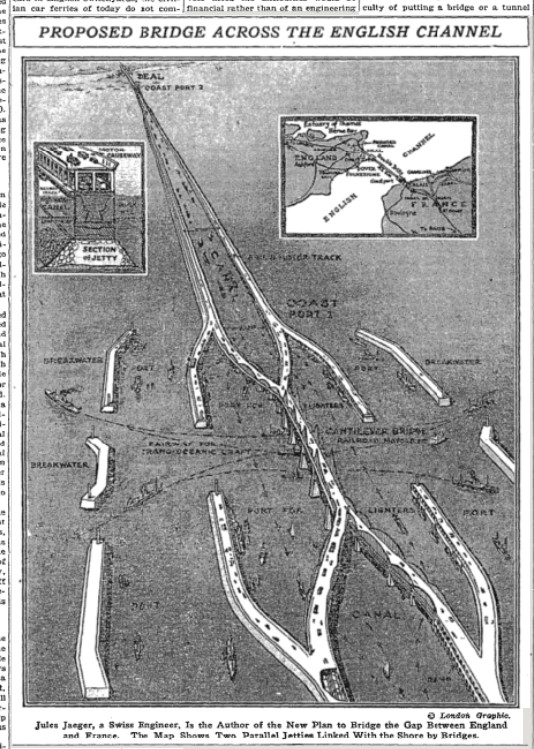
    Jules Jaeger proposed this mammoth project for bridging the English Channel: a double-jetting/bridge structure with a 1000′-wide channel between the two. Claire Price wrote a story on the idea for the New York Times on December 6, 1925, and described the structure running straight as an arrow from Calais to an eventual terminus in London, and cost $400,000,000 (or between $4-10 billion in 2018 according to the BLS CPI computer). The two jetties would rise from the channel bottom and be wide enough to each hold a double set of railroad tracks and an upper roadway for cars and freight. Price states that the colossus would be able to handle all manner of traffic in the future, even though the motor causeway is two lanes wide, and that it would be safe during wartime as the jetties would protect against torpedoes for the inner canal, though there is no mention of aircraft or other sorts of attack. 

    There’s a lot that I do not understand about the construction, not the least of which would be building a jetty 30′ wide and 150′ high/deep that was 30 miles long, times two. 

    Channel bridge jaeger full 1925

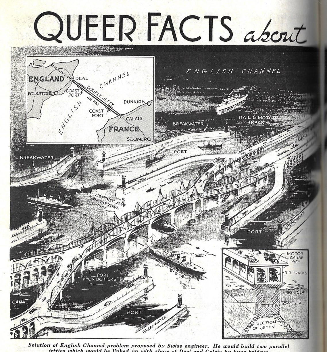
    And by a stroke of serendipity, I located (stumbled upon) an illustration of Jaeger’s channel bridge in a 1936 issue of Popular Mechanics (page 500). And again poor Mr. Jaeger goes unidentified (as a “Swiss engineer”, only).  Eleven years later the channel bridge is still alive, in some way, and with a more detailed illustration:

    Pop Mech 1936 channel bridge


    And a detail cross section showing roadway and train tracks:

    Channel bridge jaeger detail Xaection

    ·Posted by :

    ·in:


  • Note on the First Microscopical Images of Captured-and-Reproducible Sound? (1878)

    JF Ptak Science Books   Post 2743

    Only months into the invention of the phonograph by Thomas Edison (at Menlo Park in December of 1877 and patented in January 1878) Alexander J. Ellis reviewed a version of it constructed in London by Mr. Stroh, and found it, well, wanting.  Ellis (1814-1890) was a product of Eton, Cambridge, Trinity, and was a gifted mathematician, philologist, and a groundbreaking ethnomusicologist, and did see some limited utility of the machine to restricted areas of his research. In the short note he wrote for Nature in their April 18, 1878 issue1, he mostly found that the phonograph was generally flawed in its reproductive capacity, and did not venture far from this interpretation so far as the possible applications of the machine was concerned, which seems iconically short-sighted from my perch here in the future. Even though Ellis recognized that “the effects produced are sometimes startling (as in cries, coughs, laughter, music), the philosophy of the process (making a permanent impression of a very complex compound vibration, and using it as a mould to reproduce that vibration is exceedingly attractive, but at present the instrument–at least the one that I saw…” he concludes that the status of the invention “…has not risen beyond a lecture illustration or a philosophical toy”.  

    Nature 1878 Perifser Frazer

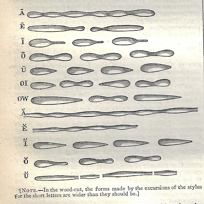
    Five weeks after this article and about four months following the patenting a visually-arresting article appeared in Nature2 which contains what I am assuming to be the first microscopic images of recorded and reproducible sound. I know that is a pretty deep qualification, but I think that’s its accurate. The article appeared as “Examination of the Phonograph Record under the Microscope” by Persifor Frazer3, who investigated what the impression of the stylus looked like as known sounds are recorded on tin foil. And so this remarkable image, showing what vowel and some dipthongs “look like”.  

    There were a number of early attempts to study what sounds look like by Lissajous and Konig, though these instruments did not produce reproducible sound but the  experimenters were able to produce characteristic traces of sounds which were of high value to folks like von Helmholtz. The premier pioneer in this area must be Édouard-Léon Scott de Martinville  (1817 –1879), a Parisian printer and bookseller [and also described in other places as a typesetter, stenographer, and “tinkerer”], who was the inventor of the earliest known sound recording device (patented 25 March 1857) known as the “phonautograph”. He was a pre-Edison Edison and was a major influence on the man, though Edison was the man who produced playback from his recordings, and Scott did not. 

    • “Scott called this process “phonauto­graphy”—the self-writing of sound. Of course he didn’t expect perfectly formed letters of the alphabet to emerge from the stylus. But he did believe the calligraphy inscribed in the soot—”the words that wrote themselves”—embodied a form of “natural stenography” that would some­day be read as easily as a sten­ographer deciphered his own jottings.”–https://www.nps.gov/edis/learn/historyculture/origins-of-sound-recording-edouard-leon-scott-de-martinville.htm
    • “Sound had been invisible and transient since the beginning of time. Scott’s phonautograph recorded it and made it both visible and perm­anent. It was a technological breakthrough, ahead of its time. He did not intend for his phon­autograms to be played back; that concept was another 20 years away. “-https://www.nps.gov/edis/learn/historyculture/origins-of-sound-recording-edouard-leon-scott-de-martinville.htm

    This instrument was not as I said designed to play back the recording; rather it was intended that the sound’s images and not the auditory experience would be studied. Scott achieved fame, recently, when archephonists were able to math the hell out of the recorded record and cranked an image to sound result—and thus, the earliest recording, Scott de Martinville  (or someone) singing a bit of “Clair de la lune”, made on 9 April 1860, which was presented for the first time in 2008.

    I saw a reference and then promptly lost it stating that the first appearance in a journal of Scott’s work occurs in 1857—except that in a later paper (1861) Scott references this event and describes giving the Academie a “paquet cachete”, a “sealed document”, which I think means that it wasn’t read to the assembly or published and was private. This turns out to be the case, the 1857 document being a manuscript, and presented at the excellent First Sounds website, here: http://firstsounds.org/publications/facsimiles/FirstSounds_Facsimile_01.pdf   It does seems though that the first and second published descriptions of the machine occur in 1858 and 1859, with Jules Lissajous’ “Report to the Society” (1858) and in Scott’s own paper in Cosmos,  “Phonautographe et fixation graphique de la voix” (1859).

    As luck would have it I own a copy of Scott’s third paper on his instrument, which appeared in the Comptes Rendus in 1861 (15 July 1861, vol 53 #3, pp 77-128), which seems in its few pages to contain a good description of the device, which would render, as Scott said, “the imprudent idea of photographing the word.”

     Notes:

    1)  “The Phonograph”, being an article in the April 18, 1878 issue of Nature, volume 17, No 442, pp 485-6 in the weekly issue of pp 481-500. 

    2)  Abstract of a paper presented at the Franklin Institute April 17, 1878, by Persifor Frazer, “Examination of the Phonograph record under the Microscope”, in Nature, May 23, 1878, p. 102. In this same issue is an excellent paper by Francis Galton, “Composite Photographs…”

    3)  Persifor Frazer was of the Philadelphia Frazers, of long and interesting lineage. A Gettysburg vet, he was in professional life mainly a geologist; he did become expert in handwriting and the detection of forgeries using photographic means. 

    4) Scott, M. E.-L. “Inscription automatique des sons de l’air au moyen d’une oreille artificielle”,  which is translated along the lines of  “Automatic Registration of Sound by an Artificial Ear”. Evidently the idea came to Scott while working/reading a textbook and having an aha! moment while reading about the human ear.  Comptes Rendus, pp 108-110, volume 53, 1861. 

    ·Posted by :

    ·in:


  • How to Fly a Farman Biplane (1910)

    JF Ptak Science Books  Quick Post

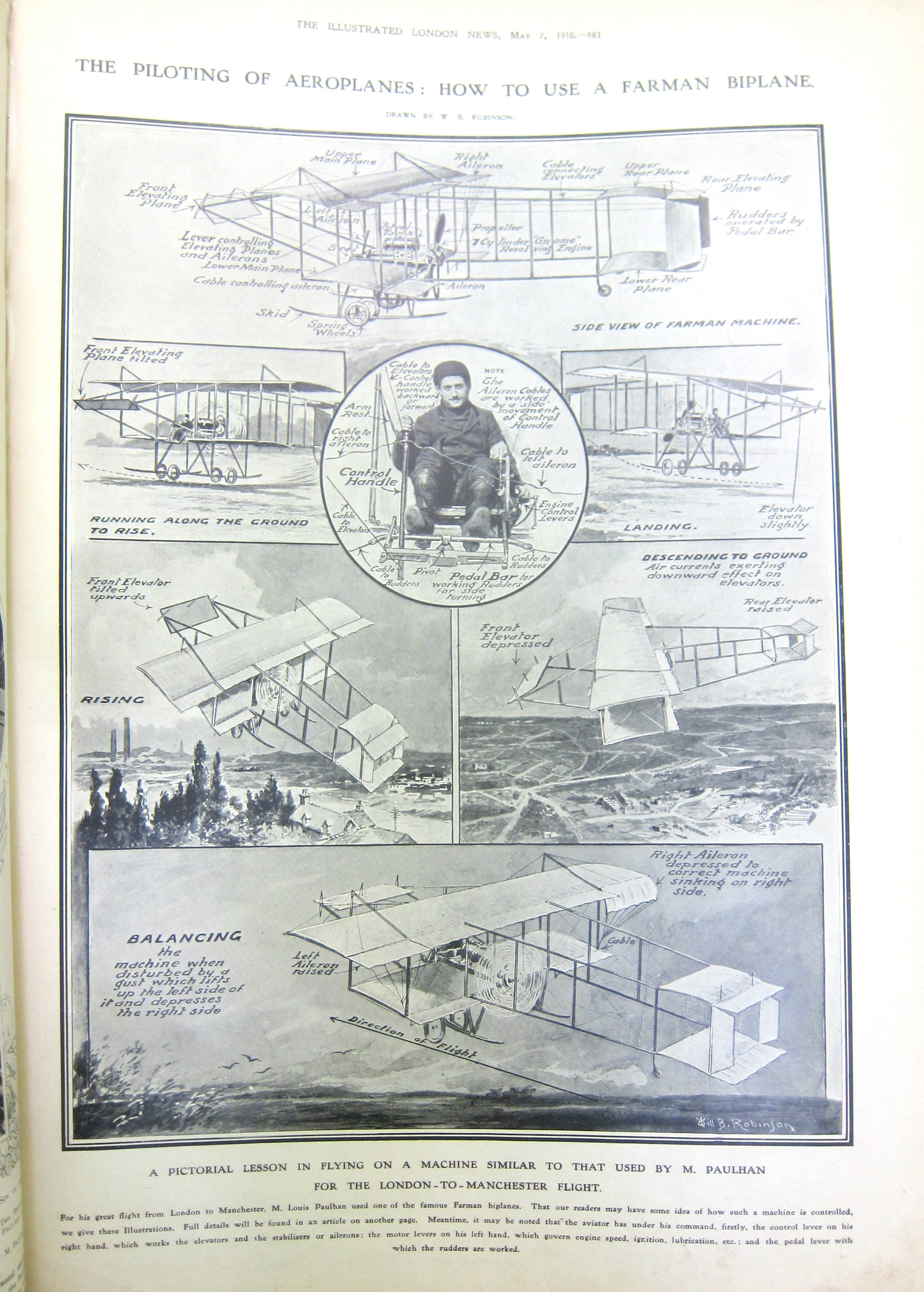
    I couldn’t resist sharing this because, well, I don’t often see a one-sheet explanation on how to fly a plane.  This is from the Illustrated London News, May 7, 1910, and concerns the Farman biplane:  

    Dataviz how to fly farman 1910


  • Great Calculators: Mental and Metal and back to Mental

    JF Ptak Science Books     Expanding Post 2739

    Two months ago I wrote on a paper that I found in a mid-century engineering journal (Minutes of Proceedings of the Institution of Civil Engineers with Abstracts of the Discussions) on the fantastic mental arithmetician George Parker. When I went to retrieve the volume to look for a different paper (on Fresnel lenses for lighthouses) I  flipped the pages to then end of the book to read through the index, and my thumb stopped on a page with a running header, “Mechanical Notations”. And lo and behold, the very familiar title was indeed a paper on a report to the Institution on Charles Babbage (1791-1871) and his “mechanical notation”, given by his son Henry P. Babbage (1824-1918).

    Well.  Babbage over the years proposed several different difference and analytical engines which indeed could be considered the first stored program Turing-complete computers. Never quite being able to get to the end of one project, and no doubt discovering along his various ways even better and more substantial designs (as well as int he pursuit of future money to build not “version 1.0” or “1.1” but “3.0”), Babbage tried within the limits of available technology to produce his heroic beast. His “mechanical notation” appears in full force in his diagrams for the design of his analytical engine, and it is there that we see his self-derived shorthand and symbols that produced and still-produce evident budgets of unknowns. The thing is, with these mechanical notations, is that they were part of a user manual, and the user manual was actually left unwritten and chiefly unexplained. And that is a problem. 

    In any event this paper by Henry Provost Babbage makes some attempt in outlining the notation, though for me it is done without success. This is further complicated by almost none of the notation presented in illustration. There were other and earlier illustrated papers (including some by Babbage himself) that stretch back at least to 1821–but this explanation of the notations leaves me a little on the outside. 

    And so we moved from the mental calculator George Bidder to the great metallic calculating engines of Charles Babbage, who takes us back to the opening biological/mental part of engineering thought via his manual-less manual, where his instructions and explanations of the interactions of thousands of perfectly manufactured precision gear works is printed but the key to which is left locked in Babbage’s head.  

    _____

    Here’s the part of the post that led to the discovery of the Babbage, both of these papers as I said appearing in the same journal volume: 

    George Parker Bidder (1806-1878) gave a lecture (without notes) explaining to the audience at the Institution of Civil Engineers in 18561 his interior practices and habits in performing absolutely prodigious and complex arithmetical feats entirely in his head. He was among the first tier of performing human calculators (like Zerah Colburn, b. 1804) mental calculations enchanted large audiences from the stages, answering seemingly impossible questions with accuracy and speed. It is in the 1856 paper (which Martin Gardner refers to as “historic2” and “valuable”) that he relates some of the practices which clarify his process–for example, one large element was that he would keep one fact in his head at a time, until it was finished, and then move on. Of course for people who did not have anything even remotely resembling this impossible ability, the information is interesting, though I have no idea how useful it may be…unless you were already a savant, that is.  Some things are just not to be known by mere mortals. Like the probably-apocryphal story of someone asking Hans Bethe how Richard Feynman had solved–on his feet–some impossible something, and Bethe responds: “First he thinks very very hard….and then he gets the answer”.) Something like that. 

    In any event, here’s the article, reproduced by Devonshire Perspectives website. My own copy is in a tightly-bound volume from the proceedings, and no doubt I would have broken the spine trying to copy the thing. That said, if anyone wants to buy this volume, it is for sale–this is a book selling site, sorta, after all.  

    The full lecture by Bidder:

    https://www.devonperspectives.co.uk/georgebidder/OnMentalCalculation.pdf

    Notes:

    1. Bidder, George Parker. “On Mental Calculation”, in Minutes of Proceedings of he Institution of Civil Engineers with Abstracts of the Discussions, volume XV, Session 1855-6, London, published by the Institution,  pp 251-280 in the 534pp volume. 

    2.  Gardner, Martin. “Mathematical Games”, in Scientific American, 216/4, April 1967, p. 117. 

    Also, I found an interesting biographical treatment of Bidder:

    • Bidder, George Parker. Mental Arithmetic. A short account of George Bidder, the celebrated mental calculator: with a variety of the most difficult questions, proposed to him at the principal towns in the kingdom, and his surprising rapid answers, etc. by George Parker BIDDER Rapid Calculator and Engineer., 1821

    It seems as though there was a separate edition of this 1856 lecture tens years later, published by Clowes:

    • Bidder, George Parker, and Institution of Civil Engineers (Great Britain). On Mental Calculation. Edited by Charles Manby. London: Printed by W. Clowes, 1866.

    And another printing somewhat later:

    • Bidder, George Parker. On Mental Calculation. London: Printed by W. Clowes, 1886.

    ·Posted by :

    ·in:

    —

  • Transatlantic Floating Airports, 1936

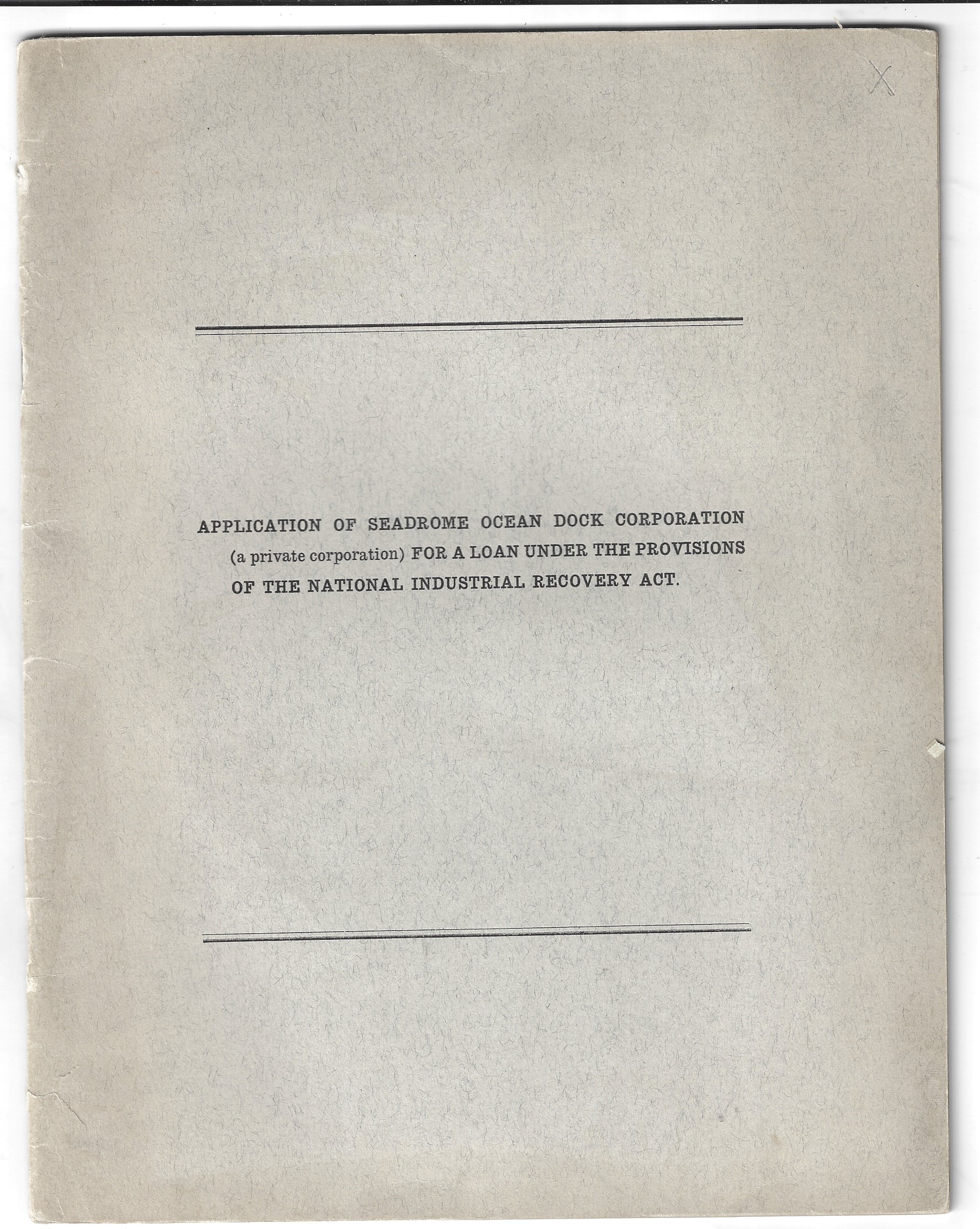
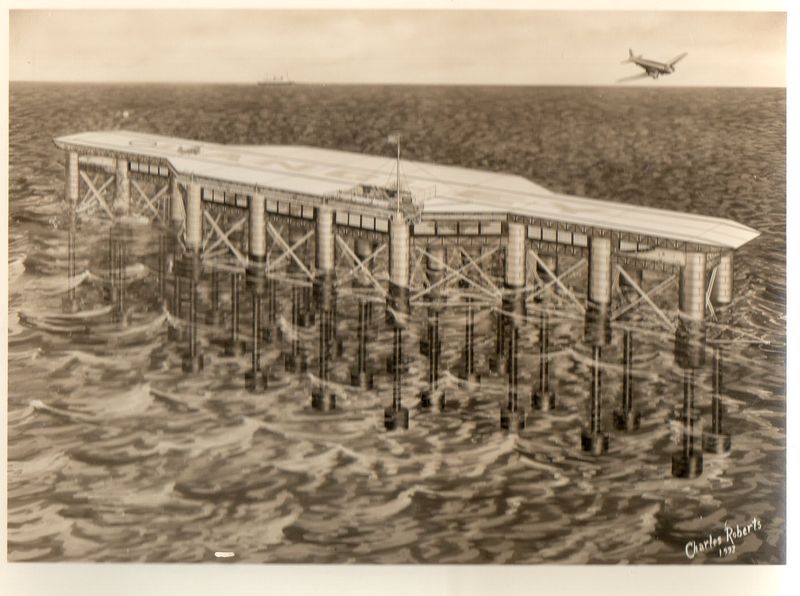
    DocFile (5)This interesting and exploratory pamphlet,  Application of Seadrome Ocean Dock Corporation (a private corporation) for a Loan Under the Provisions of the National Industrial Recovery (1933) was the result of the work of Edward R. Armstrong (1880-1955), and proposed a series of floating airports to facilitate transatlantic flights.

    The outline for this plan asks the federal government for a loan of $30 million (Depression) dollars to undertake the construction of a five floating airports transoceanic network.  “It will require the work of approximately 10,000 men per month for a period of twenty-four to thirty months”.  The labor figures did not include was what necessary to produce all of the material necessary for the project ( for reasons unknown).  Once finished the network would enable aircraft  to make it across the ocean in 18 to 36 hours.

    The members of the Seadrome Corporation estimated that the entire 30 million would be paid back by 1945,  and that the corporation would be completely debt-free.  Perhaps all of  this made sense when Armstrong first developed the plan in 1913, just ten years after the Wright brothers’ successful first in North Carolina. The idea of the floating airport girding the Atlantic was a pretty interesting idea, seeing as how the world record for sustained non-stop flight in 1913 was 11 hours (in a Maurice Farman MF-2), and that was under more-or-less optimal conditions; the speed record was 120mph, and again, optimal conditions and not sustained for hours on end.  By 1933 it seems to me that it had become obvious that non-stop transoceanic flight was coming, and coming soon.  That would of course make an investment in the Seadrome project superfluous, like building an antique, though an unnecessary one. The first transatlantic non-stop flight was made by John Alcock and Arthur W. Brown in 1919, averaging about 100mph; Lindbergh would come later to accomplish the first solo non-stop in 1927–by the early 1950’s jet aircraft would be making the trip with regularity, which means that  for most of the life of the completed Seadrome it would have been unnecessary.  I feel certain that the Seadrome–which was supposed to be paid off by 1945, though in 1933 there was no inkling on the part of the Corporation members who wrote the request for the money that a war was looming and that there would have been almost no way for them to have been made at any time between 1939 and 1945–would never have been paid for.Armstrong’s idea would get major play in the popular press from time-to-time, and discussed as a series of floating islands.  Armstrong himself would organize the Seadrome Ocean Dock Corp. in the late 1930’s, his pretty but  impractical idea (reported by Time Magazine1 in 1933 as little more than “a perennial gift to Sunday feature editors”)  finally grinding to a salty end with greater fuel capacity and efficiency in transatlantic aircraft. 

    As I said, this idea seemed pretty good when it was shiny and new, but less so as time went on and aircraft became larger, more powerful, and more efficient, capable of making the trip on their own. 
    Seadrome152

    Notes:
     

  • The Truck-Train of Short Future of 1935

    JF Ptak Science Books   Quick Post 

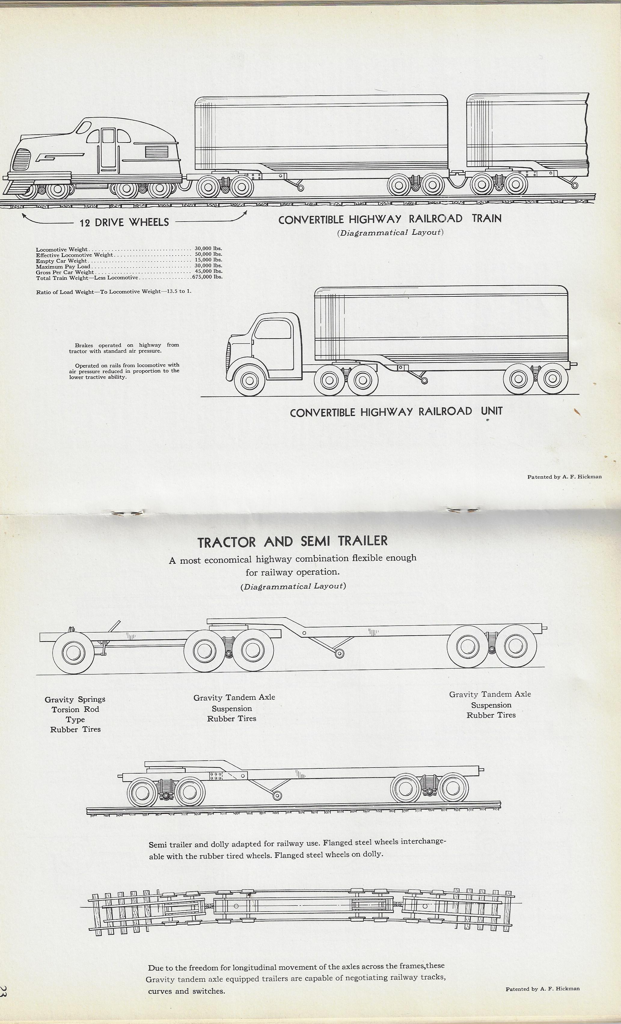
    Future train truckHere’s an interesting and pretty vision of the near-future of transportation–the truck-train. It was presented in the pamphlet Transportation of Tomorrow and its Relation to Society and Economics from 1935 (with drawings by J.F. Hickman) and presents us with smaller-version trains short-profile locomotives that hauled truck trailers where the “rail cars” could be immediately dispatched to a waiting truck at a rail head. On the one hand it seems to make a certain amount of sense if you figure the amount of time that rails throughout the country are employed, and that you could have a lot more rail traffic moving along them. On the other hand, you’d have a lot more traffic on the rails, which could lead to a of scheduling problems and delays. Also, once you got to the railhead, how exactly would trucks access the trailers in a way that was sensical and timely?  Anyway the convertible highway railroad train looks as though it would cause more problems than it would solve by re-inventing the U.S. railroad system on a smaller scale. 

    Future transportation truck train


    Future train truck


  • Prof. Langley’s Aeroplane of 1893

    JF Ptak Science Books  Quick Post

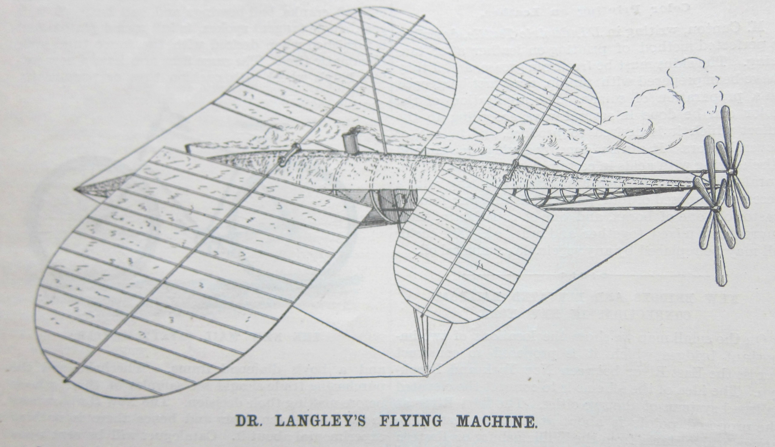
    In the Department of Victorian Understatement, the example following would be ranked…nominal. This was a general leading statement on a short one-page review of Samuel P. Langley’s1 model flying machine, found in the pages of the Scientific American for 22 April 1893 by H.E. Mead and quoting from the New York Herald. This is one of Langley’s earliest physical attempts at a flying machine, coming after four years of work (the same year work was commenced by Hiram Maxim and with the more mature work of Octave Chanute), the drawbacks of which began the article’s review:

    • “The only apparent drawback to this particular method of aerial flight is in maintaining an upright position of the apparatus, free from the ground, until sufficient velocity is attained for soaring ; and the means of alighting after flight. Other than the above mentioned difficulties (for which Professor Langley may have provided), the principle seems feasible, more especially when backed by so careful and competent authority.”

    Sci Am 1893 Langley flyer

    So, basically, it seems that what the machine was wanting was the ability to fly and land. This was never meant to hold a pilot, and was entirely experimental.  The characteristics of the model:

    • “It is 15 feet in length and 5 centimeters (or practically 2 inches) in diameter. To give rigidity to the skeleton, longitudinal ribs of stiff steel are provided, intersected at intervals by cross ribs of pure aluminum, the result being a lattice framework of great strength.”
    • “There are four boilers of thinly-hammered copper, weighing a little more than seven pounds each, and they occupy the middle portion of the fish Screws of various pitches and ranging from 20 to 80 centimeters in diameter have been experimented with, but it is not yet definitely determined which shall be adopted for· trial. With the smallest the engines develop a speed of 1, 700 revolutions a minute. With the larger ones the speed is somewhat decreased. A thin jacket of asbestos covers the upper portion of the body of the fish.”
    • “The wings, or aeroplanes, are sector-shaped and consist of light frames of tubular aluminum steel covered with China silk. The front one is 42 inches wide in the widest part and has an extreme length of 40 feet from tip to tip. The rear one is somewhat smaller. Both aeroplanes are designed to be adjustable with reference to the angle they present to the air.”

    It is interesting to note the attention this short perspective gave to the security and secrecy of the research:

    • “At the (Smithsonian) institution the strictest injunctions were laid on the watchmen to keep all intruders off the scent. The watchmen themselves were instructed to turn their backs or walk to the other end of the corridor when word was passed from the chief that some article was to be conveyed to or from the secret chamber.”

    To be fair about this some amount of secrecy was involved given the status of the kookiness in which much of the general public view the pursuit of flight–or at least the construction of large, relatively heavy models like this one. Langley had an enormous reputation to protect, and one part of that security was to keep that intact while the aeroplane was in its developmental phases, keeping the project free from derision which may have caused a problem so far as funding was concerned. That said,  Langley had conducted lectures in the great hall in which he demonstrated the flying capability of 16-gram models, so that part of his research was very public. Also, there was some proprietary work being conducted, so there’s that aspect of the secrecy bit. The Wright Brothers would be very cautious for some of these reasons, though they steadfastly used their own money generated from their bicycle shop.  (By the way “aeroplane” was not used quite yet, I believe, as a word for the aircraft, but rather as a name for the wings, and for their sections.) 

    Langley would never be on quite the right page in these earliest days of heavier-than-air powered flight, and in slightly less than a decade he would be out of the adventure altogether after his large-scale aerodrome took and immediate nosedive into the Potomac from its moored scow launching pad–it was the Wrights of course who saw a far clearer and more incisive (and brilliant) ways in the power train, material, launching, and how to control the plane once in flight and how to keep it aloft. 

    Notes:

    1. Langley has appeared often on this blog for one reason or another and if you want some background on the man simply search his name in the Google search box at upper right.  


  • A Tough Place to Work: in a Box, Submerged, Digging Muck and Boulders from a Riverbed (1870.)–Expanded

    JF Ptak Science Books   (Expanding Post 2686)

         Before the Brooklyn Bridge (begun in 1870 and opened 1883) became its incredible self, there was a lot of King-Hell work to be done before the recognizably visible bridgey part could be started. Amidst all of the thousands of bits that had to be figured out before a stone or cable could be moved, before the bridge-builder John A. Roebling (1806-1869) could begin to build, he had to construct the gigantic towers which were the great heart of the bridge on solid footing in the East River, and in order to that you had to get to the bottom of the river and then dig from there.  Roebling found the solid that he needed, but it was 80 and 40 feet below the river (on the NY and Brooklyn sides),  and so it came to pass that Roebling became one of the few U.S. experts in building the apparatus that would allow you to dig down under the bottom of a river. (Roebling became an engineer at a time when there really weren’t very many of them, and the profession was quite small–according to the U.S. census there were only 512 in the U.S.; in 1880, when the bridge was nearly completed, there were 8,600. This number expanded to 45,000 in 1900 and then 230,000 by 19301.)

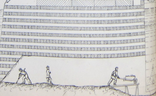
         He created what was basically an upended box, an enormous, 180’x120′ (with a 9′ ceiling that would be 6.5′ at the end) half-city-block/half acre open-bottom box, called a caisson2.  The idea was that as it was sunk to bedrock the entire structure would be braced with hundreds of thousands of bricks and then filled completely with cement. That would be the base for the 30,000 tons of masonry blocks (each about 4-7 tons) that rested on top of the 15 layers of massive timber ceiling that rested upon the brick and cement that sat on bedrock. 

         In the course of excavation the caisson would be filled with pressurized air, and then with its various modes of entry it would accommodate three shifts of about 80 men inside it, shoveling away at the muck and picking away at boulders, digging their way into the river bottom.  (Soon enough they would be blasting the boulders in the pressurized air compartments of the caisson, encapsulated by timbers waterproofed with highly combustible materials that were covered by pitch and protective layers of this and that, but that is another of the very many engineering stories that could be told in depth and not to be included in this short note.) 

         The conditions for work were oppressive, and the pressurized air was difficult to work in and had long-term ill-effects on the body for some,  the contrast between light and dark was very stark and difficult with hard shadows, the workspace demanded an immediate body-soaking sweat, the noise of the general work (excepting the blasting and boulder-breaking) was “very considerable”, the muck and water was occasionally a foot high,  and the work itself was very physically demanding.  There were over 2500 men who worked in the caissons over the 10 months that they were in use, which according to David McCullough in his excellent The Great Bridge3 meant there was an enormous turnover, 100 men a week…and no small wonder. All for $2/day, which was a little better than standard pay for laborers (and equal to about $60/day in 2017 dollars so far as I can reckon, which is sorta/kinda minimum wage for 2008.)
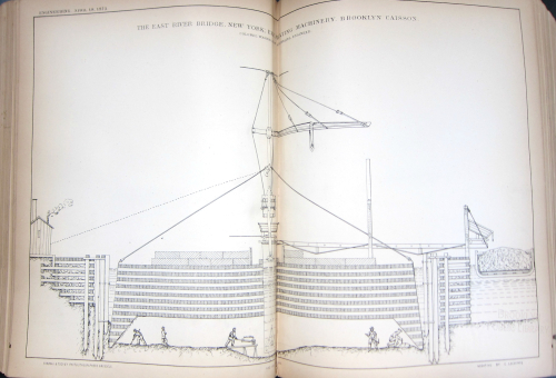
    Brooklyn caisson large engineering 1873

    • [Image Source; Engineering, 1873]

         So here they are, the guy on the right is hauling the muck to an elevator shaft at right (more visible in the full version of the woodcut, following), while another fellow shovels, and a third man strands there surveying the scene with arms folded in a pose recognized world-wide at construction scenes.  The little squares above them show the cross sections of one row 12″-thick lengths of cut lumber (laid on top of another layer of the same running at a right angle, making 15 layers in all) on top of which stone would be placed. 
    Brooklyn Bridge Caisson Engineering 1873


         It should be noted in fairness that the supervisors hardly leaned on a shovel or struck an heroic pose in the Brooklyn Bridge construction. Washington Roebling, the son of John A. Roebling and who inherited the project after his father’s very untimely death in 1869 and who was one of the best-suited men in the country to take on the job, spent many weeks in the caissons doing whatever he saw fit to be done. He was one of the relatively few workers there who was overtaken by the demands of the pressurized air, and spent the rest of his life (he died in 1929) dealing with the aftereffects of it.  

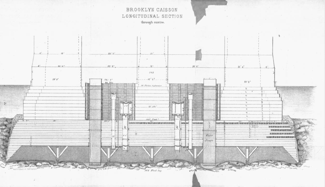
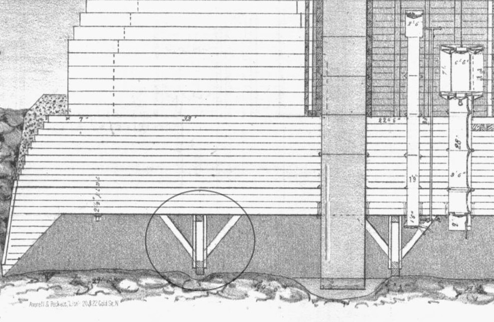
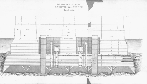
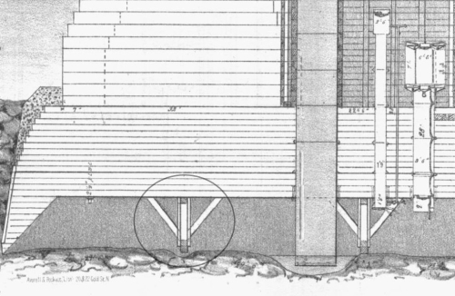
         There were air shafts and elevators and pneumatic tubing to pull out excavated earth, and as the workers dug down, the caisson would sink, and with each movement enormous blocks of granite would be placed on the top of the caisson to help it sink further.  And so this would be the process, digging down through a silty river bottom, pulling out the very heavy muck, the caisson moving down as the earth was removed, continuing the process until bedrock was reached. The caisson movement though proved to be a lot more involved than the initial design, where the edges of the thing were supposed to eat and push their way into the earth as ground was removed from around the base, with the enormous tonnage above providing the weight to push the whole thing. But it really didn’t work out that way, and the caisson(s) for the most part didn’t work their way into the riverbed. What happened was that numerous chock blocks were place and large hewn timbers place on top of them to the caisson’s ceiling. And then, once the river material was removed from the perimeter to a certain depth, the blocks would be knocked out from underneath the support, and with practice, the entire structure would set into place, moving down. And then the process would begin again, over and over.

        This is another cross section of the caisson, followed by a detail showing the blocks:
    Brooklyn bridge caisson W Roebling

    • [Image source, for the images immediately above and below:  W.A. Roebling, Pneumatic Tower Foundations of the East River Suspension, [the caissons of the Brooklyn Bridge] New York, Averell & Peckett, 1873. The full text is available from Lehigh University http://cdm.lib.lehigh.edu/cdm/ref/collection/bridges/id/1406]

    And the blocks and supports, the blocks being knocked out once all of the mud and stone had been removed from the circumference of the caisson:
    Brooklyn bridge caisson footer detail

    And then, it was all filled in, more weight was added to the top of the caisson, until that special engineering sweet spot was reached that allowed you to start building the bridge’s towers from which the bridge span would be suspended.

    This was a very difficult job and absolutely vital job, not the least of which was the problem of decompression sickness, which affected many dozens of workers, and which was not well understood.  

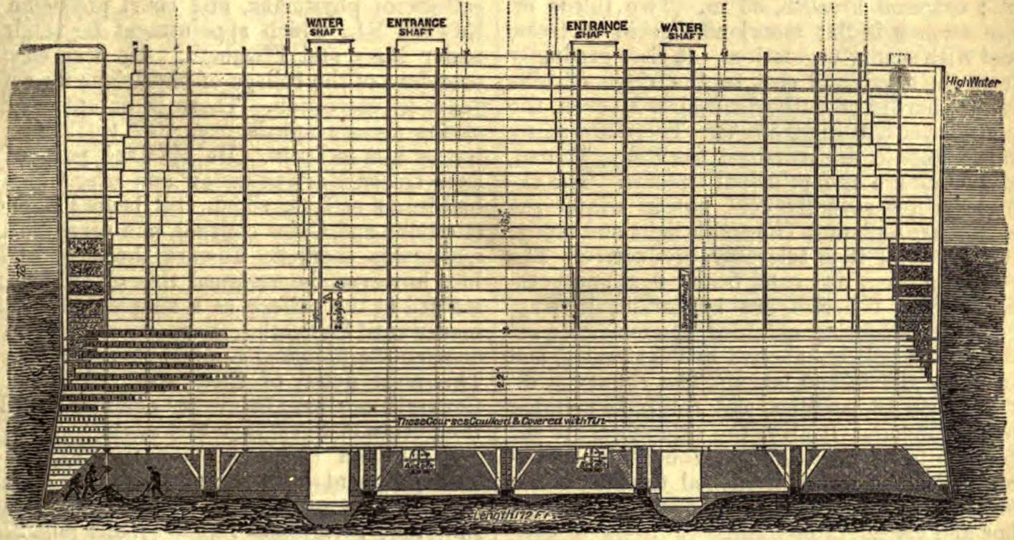
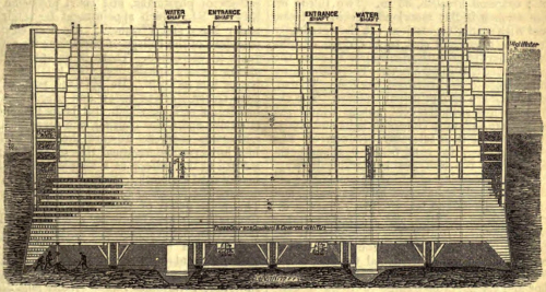
     Another image, this from The American Cyclopedia, showing the caisson at a more developed stage, and feeling that much more suffocating, and I think communicates the idea of extreme weight a little better than the others:
    Brooklyn Bridge Caisson wikimedia

    • [Woodcut/drawing illustrating caisson used by W. A. Roebling in the construction of the Brooklyn Bridge. The American Cyclopædia, v. 3, 1879, p. 557 (Fig. 2).]

         I really haven’t gotten to the most difficult jobs on the bridge. Almost at the very end of the work on the Brooklyn side there was a fire in the caisson. Up until this point there had been a number of small fire that were quickly extinguished. But nearly at completion a worker managed to ignite one of the combustible materials used to sheath the ceiling, and a small section caught fire. Given the pressurized oxygen and other factors the fire progressed to An Enormous Situation. Long story much shortened, the fire was thought to be put out until after one of the continuing series of investigation in making sure that the fire was out revealed that in fact it was not–to make matters worse, it was mostly invisible and smokeless.  Many complications and complex solutions later, the fire definitely extinguished, the time had come to finally repair the damage. The fire had eaten its way through several of the 15 layers of the wooden beamed ceiling, and those damaged parts needed to have the crystalized carbon scraped away so that the then-vacant area of wood could be filled with cement. And here it comes: it fell to 18 carpenters to pull their way as far as possible through the burned-out sections of the ceiling to scrape and chip away the burned parts. That means they were underwater, underground, in a cavernous submerged room with pressurized air, and crawling through wormholes in a 15′-thick wooden ceiling on top of which rested 30,000 tons of stone.  That, I think, was the toughest job done on the bridge. 

         30 workers were killed in various accidents during the construction of the bridge. Many considered that a bridge wouldn’t be safe unless there was some fatal blood spilled over it…and many considered that first victim to be John Roebling himself. He met his end before the physical work had been started on the bridge, killed because of a rookie situation he let himself into, he toes crushed by a ferry which led to tetanus and lockjaw, the old man dying a miserable death. He made notes and suggestions on the building of the bridge right up until the end, through the horrible stiffening of limbs and muscles as a result of the lockjaw. I guess he could’ve been considered the bridge’s first martyr. 

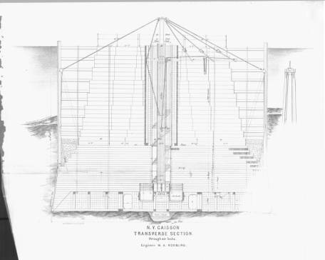
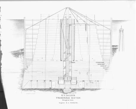
    And to balance things out a bit, here’s the transverse section of the caisson:
    Plates__Page_9

    • [Image source:  W.A. Roebling, Pneumatic Tower Foundations of the East River Suspension, [the caissons of the Brooklyn Bridge] New York, Averell & Peckett, 1873. The full text is available from Lehigh University http://cdm.lib.lehigh.edu/cdm/ref/collection/bridges/id/1406]

    Notes:

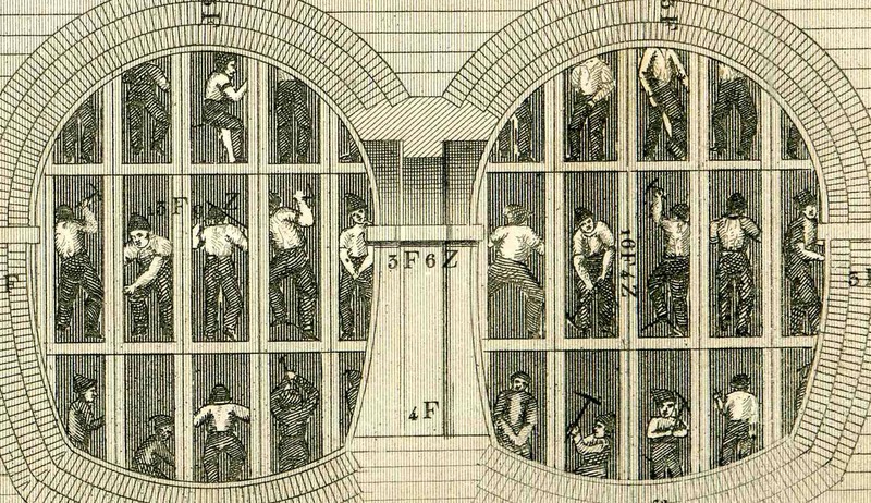
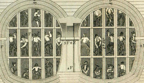
    I can’t help but include another image of a hard place to work, this one for the Thames Tunnel (from my post here: https://historyofideasblog.com/thesciencebookstore/2012/08/beautiful-technical-illustration.html)
    Tunnel detail thames


    1. Cecelia Tichi, Shifting Gears, Technology, Literature, Culture in Modern America. Chapel Hill, 1987, p 104. 

    2. “Caisson:  in architecture, a panel sunk below the surface in soffits or ceilings. In civil engineering, the term is applied, first, to a hollow floating box, usually of iron, which serves to close the entrances of. docks and basins; and second, to a box-like structure used in constructing or sinking the foundation of piers under water. Of the latter there are at least three different varieties: the ordinary, the bottomless or open, and the inverted, which includes the pneumatic. 1. The ordinary caisson is a large box with bottom and sides, made of timbers or planks, in which masonry is built and sunk to its desired position under water.”–The American Cyclopædia, v. 3, 1879, p. 557

    3. David McCullough, The Great Bridge, the Epic Story of the Building of the Brooklyn Bridge, Simon & Schuster, 1972. 

    For excellent source material see: W.A. Roebling, Pneumatic Tower Foundations of the East River Suspension, [the caissons of the Brooklyn Bridge] New York, Averell & Peckett, 1873.